Menu | Tools > SIPS Mosaics > New > SIPS Side Scan |
Tool |
|
Create a mosaic using the SIPS Side Scan engine to process side scan data converted into HIPS format.
SIPS Side Scan engine processes side scan using imagery corrections such as TVG, gain and despeckle as well as beam pattern correction to create mosaics from selected track lines.
Related commands:
Create SIPS Mosaic using Backscatter
Interface
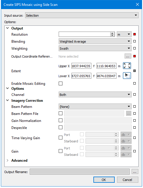
A new mosaic using backscatter data is created using the Create SIPS Mosaic using Side Scan dialog box.
Procedure
1. Zoom/pan to display the extents of the data that you want included in the mosaic.
2. Select one or more track lines. If no track lines are selected, the mosaic will be created using on all open track lines.
3. Select the New SIPS Mosaic using Side Scan command.
The Create Mosaic dialog box is displayed.
4. Set the Input Source for the mosaic.
5. Set a Resolution and a Coordinate Reference System for the mosaic.
6. Enter Options, Imagery Corrections and Advanced options as they relate to the type of mosaic engine being used.
See SIPS Mosaic Options for details on settings.
7. Click Browse and set name and path for the output mosaic.
Option | Description |
Input Source | If lines were selected before opening the dialog box, the Input Source field is set to Selection. If no lines were selected, the mosaic will be created from all open lines. The Selection setting can be changed to All Track Lines. |
Output | |
Auto Resolution | Applies only to mosaics created with GeoCoder engine. If selected, a resolution will be set based on density of data. In this case, the Resolution option is disabled. |
Resolution | 1. Type a numerical value for the resolution of the mosaic image. 2. [Optional] Change the units of resolution from the list to the right of the Resolution field. A resolution must be set for mosaics from side scan or backscatter data. |
Blending | The method used to blend pixels together. The default value is Weighted Average. Select from: • Weighted Average: Blend overlapping pixels based on a weighted average value • Highest weighted: Use only the highest-weighted pixel in the output, no blending • Overwrite: Use the last input pixel value in the output, no blending |
Weighting | The method used to weight pixels across a single ping. The default value is SWATH. Select from: • Swath: Weighting is based on sonar geometry where Nadir has a low weight, off-nadir has the highest weight, and a decay function is used to decrease weighting out to the swath edge • Fixed: All values are weighted equally across the ping (primarily for SAS imagery). |
Output Coordinate Reference System | 1. Set the horizontal coordinate reference system for the output mosaic. An output CRS must be set for all mosaics. |
Extent | Displays the ground coordinates of the current view of data in the Display window. These are displayed as Lower Left and Upper Right X and Y values. This is the default setting. To change the area of the mosaic: 1. Click the Pick from screen button. 2. Use the cursor to drag a box around an area to mosaic. Coordinates for the area will update as you draw, resize or move the box. The mosaic created will be within the extents of the box. To restore the default stetting, click the Use screen extents button. |
Enable Mosaic Editing | 1. Select the check box to enable editing of the mosaic after creation. |
Options | |
Channel | 1. Select Port channel, Starboard or Both to be read to mosaic. (Does not apply to Backscatter mosaic) |
Local Absorption | Correction for transmission loss using temperature and salinity values. • Set temperature value in degrees. Default value is 8.00. • Set salinity value as parts per thousand. Default value is 35 parts per thousand. (Applies to Backscatter mosaic only.) |
Surface | The path to the surface used to compute the local bottom slope used in the calculations of real incidence angle and ensonified area. The default elevation band will be used. 1. Click Browse and locate surface to be used. If a surface is not set, the default value is to use the processed bathymetry. (Applies to Backscatter mosaic only.) |
Imagery Type | The type of imagery to be processed. Select from Beam average, Side scan or Time series. The default value is Time Series. (Applies to GeoCoder mosaic only.) |
Imagery Correction | |
Beam Pattern | Use a beam pattern file to uniformly remove angular artifacts from sonar data. 1. Select Port channel, Starboard or Both have beam pattern correction applied. (Does not apply to Backscatter mosaic) |
Beam Pattern File | Select the check box to enable and locate a beam pattern file. When a file is set here, the options to update or overwrite can be activated in Beam Pattern File Operation field |
Beam Pattern File Operation | If the beam pattern file selected in the field above already exists, you can set the fate of the existing file. • Update: Updates the file with the new line information. This option can accumulate many lines over many surveys. • Overwrite: Overwrites the existing file with a new beam pattern file from the current lines. • Use Existing: Uses the existing file and does not update it. The default value is UPDATE. (Applies to Backscatter mosaic only.) |
Anti-Aliasing | Anti-aliasing can minimize distortion artifacts when representing the high resolution imagery at a lower resolution. 1. Enable the check box to smooth mosaic using anti-aliasing. (Applies to GeoCoder mosaic only.) |
Angle-Varying Gain | Use a moving average filter to remove the angular response of sediment from the imagery. 1. Enable the check box and then select the type of filter from the list. (Does not apply to side scan mosaic) |
Despeckle | Smooths imagery by removing “noise”. Pixels are removed If they have an intensity level outside a specified strength compared to their neighbouring intensity levels. 1. Enter a numeric value specifying the strength of the despeckle filter as a percentage for despeckling the output mosaic pixels. (Applies to side scan mosaic only.) 2. Select Weak, Strong, Moderately Strong or Very Strong from the list. Default is None. (Applies to GeoCoder mosaic only.) (Does not apply to Backscatter mosaic) |
Gain | Apply a uniform gain correction without applying the any time-dependent gains by using only the Gain controls. 1. Enable the check box to apply Gain. 2. Select to apply to Port , Starboard or Both, in side scan. (Does not apply to Backscatter mosaic) |
Time-Varying Gain | Gain varied by time values is applied so that inner-most samples have the least gain and the outer-most samples have the highest gain correction. 1. Enable the check box to apply TVG. 2. Select to apply to Port , Starboard or Both, in side scan. (Does not apply to Backscatter mosaic) |
Window Size | This option is activated if Angle-Varying Gain check box is selected. 1. Set the number of across track samples to include in the moving average filter. (Applies to GeoCoder mosaic only.) |
Advanced | |
Use Bathymetry to Register | Enable the check box to register the imagery using co-acquired bathymetry. This is only applicable if the lines contain processed bathymetry. (Applies to side scan mosaic only.) |
Gyro Source | Set the heading source to be used for processing a side scan mosaic. Default setting is Automatic, which will apply Towfish gyro first, then Ship gyro, then Course Made Good. Any of these options can be applied instead: • CMG: Course made good, calculated from position • SHIP: Ship gyro sensor • FISH: Towfish gyro sensor |
Smooth Gyro | Enable check box to apply smoothing coefficients for gyro data. (Does not apply to Backscatter mosaic) |
Sound Velocity | Set a numeric value for sound velocity in distance per second. The default value is 1500 m/s. Supported units: metres/second. (Does not apply to Geocoder mosaic) |
Extrapolate time | Enable the check box to extrapolate heading and navigation data at the beginning and end of lines. Set a value for the time. (Applies to side scan mosaic only.) |
Filter Data | Enable the check box to filter the final compensated intensities of the mosaic using range values. • Set Minimum value for the range (default value is -100dB) • Set Maximum value for the range (default value is 0dB. |
Ratio | (Applies to side scan mosaic only.) |
Across- track / Altitude limit | (Applies to side scan mosaic only.) |
Across-track distance limit | Filter to excluded a fixed distance across-track from nadir, regardless of altitude. Enable the check box and set the • Minimum values below this distance from nadir will be filtered. • Maximum- values greater than this distance from nadir will be filtered (Applies to side scan mosaic only.) |
Altitude Offset | (Applies to side scan mosaic only.) |
Transducer 1 Angle filter | (Applies to Backscatter mosaic only.) |
Transducer2 Angle Filter | (Applies to Backscatter mosaic only.) |
Surface | (Applies to GeoCoder mosaic only.) |
Filter Angle from Nadir | Enable the check box to use an angle across-track from directly below the ship (0 degrees) to set how much data is included in the beam pattern file. Value applies to both port and starboard angles. Set minimum value in degrees of the angle from nadir. Default is 0 degrees. Set maximum value in degrees of the angle from nadir. (Applies to GeoCoder mosaic only.) |
Output file name | Click Browse and set name and path for the output mosaic. There must be a defined name or the mosaic will not be created. |
Related Commands:
•
• See also:
• Create SIPS Backscatter Beam Pattern file
• Create GeoCoder Beam Pattern File
Menu | File > New > Project |
Tool |
|
Projects in HIPS and SIPS are organized into the following hierarchy within a HIPS repository:
Project / Vessel / Day / Line
For more information on project structure, see PVDL Structure.
The new project creation process generates a HIPS Project File (*.hips). Existing projects that were saved as *.hpf files, are converted to *.hips when you first open them in HIPS and SIPS.
Vessel and /Day layers can be added to an existing project. Day and Line layers can be renamed, taken out of the active project or deleted outright.
All projects must contain a vessel file. See Create a New HVF.
You can be connected to more than one project repository at one time, using the commands from the right-click menu in either the New Project or Open Project dialog box.
Projects created earlier than HIPS 9.0 that were saved as *.hpf files. These, are automatically converted to *.hips when you first open them in HIPS and SIPS. |
Procedure: Step 1


 on Standard toolbar