Tool | CZMIL > One Step CZMIL Processing (Tools window) |
The One Step CZMIL Processing process model is used to process a CZMIL dataset from raw data to a clean CSAR point cloud in a single step. This process model is a collection of the following individual CZMIL processes available in the Tools window chained together, with a number of predefined values, in the order that the processes must be run.
• Generate Turbidity and Reflectance Outputs
All settings and values in each process can be defined in this single process model and run as a single iteration to create a point cloud that can then be analyzed in BASE Editor using the Subset Editor.
CARIS Batch process: N/A
Interface
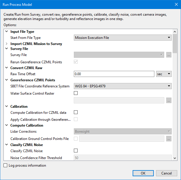
The options in this process model include:
Option | Description |
|---|---|
Input File Type | |
Start From File Type | This option is used to choose whether the process model will begin processing from a mission execution file or from a survey file. When starting from a mission execution file, the process model automatically imports the mission into a new survey file and then applies Georeference CZMIL Points. This is because the survey file is the required format for the other processes in the process model. If a survey file already exists, that file can be used instead as the starting point and Georeference CZMIL Points can optionally be applied or not prior to running the other processes in the model. The selection made for this option determines whether other fields in the dialog box are enabled or not: • If • If |
Import CZMIL Mission to Survey | |
Mission Execution File | The name and location of the mission execution file for the CZMIL lidar dataset that will be used if running the process model from a mission execution file. 1. Click the browse button (...) to launch an Open file dialog box. 2. Navigate to the relevant file. 3. Click Open. |
SBET File(s) | The name and location of the SBET file containing the navigation points of the survey. If more than one file was used for the survey, each file can be added to the list. If more than one file is specified, they can be ordered in the list and applied during import in the order they are listed. 1. Click the Add File button 2. Use the Up- and Down-Arrow buttons to adjust the order of the items in the list. The Remove button |
Processing Folder | The output location for processed survey files. |
SBET RMS File(s) | The name and location of the SBET RMS file for the CZMIL dataset. More than one file can be added to the list if multiple files were used for the survey. If more than one file is specified, they can be ordered in the list and applied during import in the order they are listed. 1. Click the Browse to File button 2. Use the Up- and Down-Arrow buttons to adjust the order of the items in the list. The Remove button |
Survey Name | The name to assign to the resulting survey file if the default name is not being used. If this option is not specified, the output folders and files will automatically use the file name of the mission execution file appended with the current date. |
Camera Raw Folder | The location of any camera images from the survey in PhaseOne IIQ raw format that should be copied over during import. |
Buffer Time | The maximum allowable difference (in seconds) in start times between the CZMIL LRAW files and flight lines stored in the CZMIL Mission Execution files. If not set, the default value of 5 will be used. |
Survey File | |
Survey File | The name and location of the survey file for the CZMIL lidar dataset that will be used if running the process model from an existing survey file. 1. Click the browse button (...) to launch an Open file dialog box. 2. Navigate to the relevant file. 3. Click Open. |
Rerun Georeference CZMIL Points | Enable this option to rerun the Georeference CZMIL Points process on the survey data that was previously georeferenced. 1. Click the check box to enable the option. |
Convert CZMIL Raw | |
Raw Time Offset | The time offset to apply to navigation timestamps when converting the data. 1. Type a value in the field. 2. Select a unit of time from the drop-down list. |
Georeference CZMIL Points | |
SBET File Coordinate Reference System | The Geographic coordinate reference system (CRS) used to store the Applanix SBET file. This information is stored in the header of the CPF file as the CRS of the CPF file depends on the CRS of the SBET file and is used for future processing, such as exporting the CPF to LAS. NAD 83 and WGS 84 are currently supported. 1. Select a CRS from the drop-down list. |
Water Surface Control Raster | Apply a GeoTIFF raster surface (.tiff) as a representation of the water surface. This is used to help determine the depth of the seafloor when water shots have missing or unreliable surface returns. The values in the raster that will be used for the water surface is controlled by the bands specified for the Water Surface Control Elevation Band and the Water Surface Control Range band. This tells the process where to find the elevation values and the range of values within the elevation band that will be used. 1. Click the check box to enable the option. 2. Click the browse button (...) to launch the Open File dialog box. 3. Navigate to the relevant raster file and click Open. |
Calibration | |
Compute Calibration for CZMIL data | Enable this option to compute the calibration values for the selected survey file. The calibration values can be applied now or at a later time. 1. Click the check box to enable this option. |
Apply Calibration to CZMIL data | Enable this option to apply calibration values to the selected survey file. The calibration values to be applied can be from a previous computation or from the current run of the process model. 1. Click the check box to enable this option. |
Compute Calibration | |
Lidar Corrections | The corrections to be applied when computing calibration. The options include: • Boresight - Adjusts the misalignment (Boresight) angles between IMU and Sensor. This correction should be applied whenever the system is re-installed or components are replaced. • Production - Adjusts the trajectory to correct for misalignments between flightlines. This correction should be applied to improve matching of project data. • Bathy LookUp Table - Adjusts the bathy look-up-table coefficients by comparing CZMIL data against ground control points (GCP). This process requires the Ground Control Points File option to be populated with a GCP file in ASCII format. • Boresight Plus Range In Air: Adjusts the misalignment (Boresight) angles between IMU and Sensor, along with Range scale and offsets. This correction should be applied whenever the system is re-installed or components are replaced. This process requires the Ground Control Points File option to be populated with a GCP file in ASCII format. • Sensor Calibration - Adjusts the intrinsic sensor calibration parameters, including angular and range corrections between channels. This option should only be used after sensor repairs or when advised by Teledyne. This process requires the Ground Control Points File option to be populated with a GCP file in ASCII format. This option is only enabled if the Compute Calibration for CZMIL data option is selected. |
Calibration Ground Control Points File | A file containing ground control points. LMS uses ground control points to adjust the calibration parameters during the calibration process. LMS accepts control points given with their IDs and standard deviations. The control points should be in an ASCII file as a list of coordinates. Each control point should be written on a separate line. LMS skips lines starting with the # symbol. There are several supported formats for an ASCII file with a set of control points: • 3 columns: X, Y, Z • 4 columns: ID, X, Y, Z • 6 columns: X, Y, Z, Std_Dev (X), Std_Dev (Y), Std_Dev (Z) • 7 columns: ID, X, Y, Z, Std_Dev (X), Std_Dev (Y), Std_Dev (Z) This option is only enabled if the Compute Calibration for CZMIL data option is selected. |
Classify CZMIL Noise | |
Classify CZMIL Noise | Enable this option to assign a noise confidence value to all points in a CZMIL dataset. This value can then be used for filtering purposes. 1. Click the check box to enable this option. |
Noise Confidence Filter Threshold | The filter tolerance that will be used to determine whether or not points in the survey will be included in the output dataset. 1. Type a value in the field. |
Outputs | |
Elevation Surface | Enable this option to generate an elevation surface in CSAR format using the elevation values in the CZMIL dataset. 1. Click the check box to enable this option. 2. Click the browse button (...) to launch an Save file dialog box. 3. Specify a name and location for the file. 4. Click Save. |
Elevation Image | Enable this option to generate a raster image in TIFF format using the elevation values in the CZMIL dataset. 1. Click the check box to enable this option. 2. Click the browse button (...) to launch an Save file dialog box. 3. Specify a name and location for the file. 4. Click Save. |
Elevation Standard Deviation Image | Enable this option to generate a raster image in TIFF format using the elevation and standard deviation values in the CZMIL dataset. 1. Click the check box to enable this option. 2. Click the browse button (...) to launch an Save file dialog box. 3. Specify a name and location for the file. 4. Click Save. |
Turbidity Surface | Enable this option to generate a raster surface in CSAR format using the turbidity values in a CZMIL dataset. 1. Click the check box to enable the option. 2. Click the browse button (...) to launch an Save file dialog box. 3. Specify a name and location for the surface. 4. Click Save. |
Turbidity Image | Enable this option to generate a raster image in TIFF format using the turbidity values in the CZMIL dataset. 1. Click the check box to enable this option. 2. Click the browse button (...) to launch an Save file dialog box. 3. Specify a name and location for the file. 4. Click Save. |
Reflectance Surface | Enable this option to generate a reflectance surface in CSAR format using the reflectance values in a CZMIL dataset. By default, the file will be created using the same name and location as the survey file. 1. Click the check box to enable the option. 2. Click the browse button (...) to launch an Save file dialog box. 3. Specify a name and location for the surface. 4. Click Save. |
Reflectance Image | Enable this option to generate a raster image in TIFF format using the reflectance values in the CZMIL dataset. 1. Click the check box to enable this option. 2. Click the browse button (...) to launch an Save file dialog box. 3. Specify a name and location for the file. 4. Click Save. |
Output Coordinate Reference System | The coordinate reference system (CRS) that will be used to create the output images and/or surfaces. 1. Click the Browse button (...) to launch the Select Coordinate Reference System dialog box. 2. Select a CRS from the list. 3. Click OK. |
Camera Images for Subset Editor | • Convert Camera Images from raw format to JPEG (TIFF or PNG): Enable this option to convert camera images captured during a survey from PhaseOne IIQ raw format to a common image format. Click the check box to enable the option. • Image Format: The output format for the converted images. If this option is not specified, the images will be converted to JPEG by default. |
Resolution | The ground resolution that will be used to create the raster outputs. • Value: Type a resolution value in the field. • Unit: Select a unit of measure for the resolution value from the drop-down list. |
Advanced Options | |
Water Surface Control | The water surface control band settings for the input raster. • Elevation Band: The name of the band in the water surface control raster that contains the elevation values to be used as the water surface. The points that will contribute to the water surface is defined by the values found in the specified Range Band. • Range Band: The name of the band in the water surface control raster that contains distances above and below the water surface that are considered to be within the margin of error for being the water surface. This defines the range of elevation values that will contribute to the water surface determination when processing the points in the specified Elevation Band. If this option is not specified, range estimates are automatically calculated for each point in the specified raster. The range will be clipped to the water surface window size specified in the lidar parameters for the dataset. 1. Type the name of each band from the control raster in the relevant field. |
Topography Options | The elevation and reflectance topography data channels and data returns in the survey data from which values will be read when generating the output surfaces and images. 1. Click to populate the check box of each channel to be included. 2. Click to populate the check box of each return to be included. |
Bathymetry Options | The elevation and reflectance bathymetry data channels and data returns in the survey data from which values will be read when generating the output surfaces and images. 1. Click to populate the check box of each channel to be included. 2. Click to populate the check box of each return to be included. |
Common Options | |
Log process information | Create a log file containing the options specified when the process was run. The location of the log file is determined by the Logs setting in Tools > Options > Files and Folders. 1. Click the check box to enable this option. |
Procedure
1. Double-click the One Step CZMIL Processing process model in the Tools window.
The Run Process Model dialog box is displayed, populated with the One Step CZMIL Processing process model.
2. Choose the type of file that will be used to start processing.
3. Depending on the selected file type, either:
• select a Mission Execution File and define the necessary options, or
• select a Survey File.
4. Define any other necessary options.
5. Click OK.
A progress dialog box is displayed providing information about each process as it is run. Additional information is also provided via messages in the Output window.
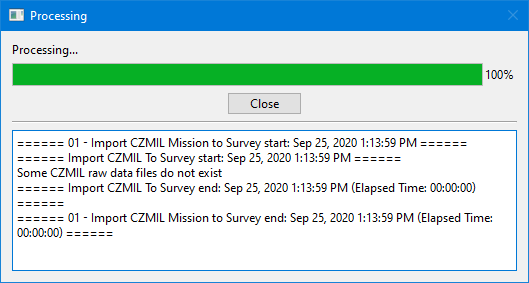
6. Click Close to complete the process.
The dialog box is closed and the new point cloud is displayed in the 2D View. If starting from a mission execution file, a new survey file is also created and displayed.
 to select a file to add to the list.