Tool | CZMIL > 06 - Generate Elevation Outputs (Tools window) |
The Generate Elevation Outputs process model is used to create one of three possible output formats representing the elevation and/or standard deviation values in the CZMIL dataset. The raster images are created using the TIFF format and the surface in CSAR format.
CARIS Batch process: N/A
Interface
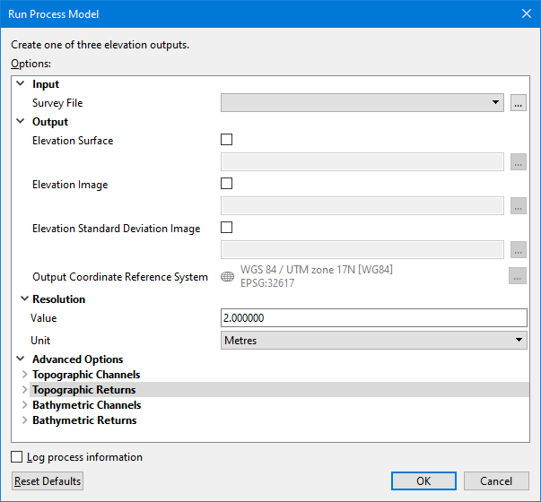
The options in this process model include:
| Option | Description |
|---|---|---|
Input | Survey File | The name and location of the survey file containing the survey lines of CZMIL data. If a survey file is open in the application, a drop-down list is also provided for this option. The drop-down list allows a survey layer open in the application or the current selection (if a survey line is selected) to be used as the input survey. 1. Click the browse button (...) to launch an Open file dialog box. 2. Navigate to the relevant file. 3. Click Open. |
Output | Elevation Surface | Enable this option to generate a raster surface using the elevation values in the CZMIL dataset. A name and location for the new surface file must be specified. 1. Click the check box to enable the option. 2. Click the browse button (...) to launch a Save file dialog box. 3. Specify a name and location for the output file. 4. Click Save. |
Elevation Image | Enable this option to generate a raster image in TIFF format using the elevation values in the CZMIL dataset. A name and location for the new elevation image file must be specified. 1. Click the check box to enable the option. 2. Click the browse button (...) to launch an Open file dialog box. 3. Specify a name and location for the output file. 4. Click Save. | |
Elevation Standard Deviation Image | Enable this option to generate a raster image in TIFF format using the elevation and standard deviation values in the CZMIL dataset. A name and location for the new elevation and standard deviation image file must be specified. 1. Click the check box to enable the option. 2. Click the browse button (...) to launch an Open file dialog box. 3. Specify a name and location for the output file. 4. Click Save. | |
Output Coordinate Reference System | The coordinate reference system (CRS) to apply to the output file. 1. Click the Browse button (...) to launch the Select Coordinate Reference System dialog box. 2. Select a CRS. 3. Click OK. | |
Resolution | Value | The ground resolution that will be used to create the output file. 1. Type a value in the field. |
Unit | The unit of measure that will be used for the resolution value used to generate the output file. 1. Select a unit of measure from the drop-down list. | |
Advanced Options | Topographic Channels | The topography data channels of the data returns from which values will be read when generating the output surface and/or image. 1. Click to populate the check box of each channel to be included. |
Topographic Returns | The topography data returns in the survey data from which values will be read when generating the output surface and/or image. 1. Click to populate the check box of each return to be included. | |
Bathymetric Channels | The bathymetry data channels of the data returns from which values will be read when generating the output surface and/or image. 1. Click to populate the check box of each channel to be included. | |
Bathymetric Returns | The bathymetry data returns in the survey data from which values will be read when generating the output surface and/or image. 1. Click to populate the check box of each return to be included. | |
Log process information | Create a log file containing the options specified when the process was run. The location of the log file is determined by the Logs setting in Tools > Options > Files and Folders. 1. Click the check box to enable this option. | |
Procedure
1. Double-click the Generate Elevation Outputs process model in the Tools window.
The Run Process Model dialog box is displayed, populated with the Generate Elevation Outputs process model.
2. Navigate to the relevant Survey File.
3. Click the check box of the product type(s) to be created.
4. Specify a name and location for each output type.
5. Specify the Resolution Value and Unit for the output.
6. Select the Topographic and Bathymetric Channels and Returns to be included.
7. Click OK.
A progress dialog box is displayed providing progress information as the images are generated. Similar information is also reported in the Output window.
8. When finished, click the Close button to close the dialog box and complete the process.