![]() CARIS HPD Paper Chart Editor
CARIS HPD Paper Chart Editor
This command is only available if the HCRF module is enabled. |
Menu | File > Export > HCRF |
Export a chart to an Hydrographic Chart Raster Format (HCRF) file.
The HCRF chart is saved to a location that is set in the Raster Chart Service (RCS) control file.
The RCS control file (rcsControl.xml) and all files related to HCRF export are located in the HCRFConfig folder. This folder is referenced by the HRCFconfig environment variable. For more information on HCRF files, see Support Files.
HCRF export requires that specific chart, sheet and panel attributes be defined and specific cartographic features be added.
HCRF-specific features and attributes must be added to the schema using the |
Attributes
Chart attributes are mapped to HCRF attributes through the caris2hcrf_metadata.xml file in the HCRFConfig folder. Mandatory attributes are listed in the table below.
Attribute | Acronym | HCRF Attribute |
|---|---|---|
Chart | ||
Partner Country | PUBCON | Chart/File identifier: Country of origin for this version |
Edition Date | EDDATE | Chart/File identifier: Edition date |
Chart Number | CHTNUM | Chart/File identifier: Chart number |
Main Title | CTITL1 | HDR: General Information: Main title |
Palette ID | HCRPAL | PAL lookup table record |
Chart Type | CHTYPE | n/a (does not match any HCRF attribute but is necessary for the export process) |
Sheet | ||
Type of Sheet | TSHEET | n/a (does not match any HCRF attribute but is necessary for the export process) |
Panel | ||
Panel Number | PANNUM | Pxx.General Data.Sub-panel number used for xx in .Pxx and .Nxx file names.1 |
Panel Name | PANNAM | Pxx.General Data.Chart panel title |
Panel Type | PANTYP | Pxx |
Projection | PRJCTN | • Pxx.General Data.Projection • Pxx.General Data.Projection parameter 1 • Pxx.General Data.Projection parameter 2 • Pxx.General Data.Projection parameter 3 • Pxx.General Data.Projection parameter 4 |
Scale | PSCALE | Pxx.General Data.Projection.Scale |
Horizontal Datum | DATUM | Pxx.General Data.Projection.Horizontal datum |
Depth Units | DEPUNT | Pxx.General Data.Projection.Depth units |
Depth Datum | DEPDAT | Pxx.General Data.Projection.Depth datum . |
Height Units | HGHTUN | Pxx.General Data.Projection.Height units. |
Height Datum | HGHTDA | Pxx.General Data.Projection.Height datum. |
1 Pxx and Nxx files are created for each panel and note in the HCRF chart. The "xx" notation is the panel or note number.
Cartographic Features
Specific line and point features that define the HCRF chart must be added. Some features are mandatory and others are optional. Line features must be closed and cannot intersect each other.
This table lists these features along with corresponding HCRF features and digitizing requirements.
Chart Feature | HCRF Feature | Requirements |
|---|---|---|
Lines | ||
RNC Chart Boundary |
| The RNCCHART line must enclose the entire chart. |
RNC Panel Boundary |
| RNCPANEL is an enclosed line that defines the section of a panel that can be used for navigation in a Raster Nautical Chart image. The chart must contain at lease one RNCPANEL line. RNCPANEL lines must be inside or touching the RNCCHART line. RNCPANEL lines that cross the 180° meridian must contain RNCSUBPANEL lines on both sides of the meridian. RNCPANEL lines cannot intersect or be enclosed inside another RNCPANEL line. RNCPANEL lines cannot have more the 30 vertices. |
RNC Sub-Panel |
| The RNCSUBPANEL area within an RNCPANEL must be the exact same area as the RNCPANEL. RNCSUBPANEL lines must be added to both sides of the 180° meridian if the RNCPANEL line crosses the meridian. RNCSUBPANEL lines cannot have more the 30 vertices. |
RNC Note Boundary |
| RNCNOTE defines a box around a note image in a chart, for use in a Raster Nautical Chart. RNCNOTE must be inside or touching an RNCPANEL line. |
RNC Source Data Diagram Graphic Boundary |
| RNCSDDG defines the boundary of a source diagram. RNCSDDG lines must be inside or touching an RNCPANEL line. |
Point | ||
RNC Test Point |
| At least one RNCTESTPOINT must be inside or touching the boundary of every panel. The maximum number of RNCTESTPOINTs in an RNCPANEL or RNCSUBPANEL is 10. |
Related commands:
• • • • • | • • • • • |
Interface

Property | Description |
|---|---|
Raster Chart Service | A list of raster chart services from the RNC control file. Select a raster chart service from the list. |
File Issue Date | The File Issue Date is the date when the current version of the file is published. The default date is the current YYYMMDD. Select a date from the drop-down calender. |
Output Template | Use an output template file to determine what layers are include in or omitted from the chart. For more information see Output Templates. Select a file from the list or select <Create and Manage> to create a new file or edit an existing one. |
Procedure
1. Select the chart layer.
2. Select the Export Chart to HCRF command.
3. Set any other necessary properties and click OK.
A message is displayed in the Output window informing you that the export was successful.
The HCRF chart is saved to a location that is set in the <latestRootFolder> element in the RCS control file (rcsControl.xml).
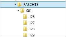
The charts are organized according to the standard HCRF directory structure.
When a chart is exported, a RASCHTS folder is created. This is an example of a RASCHTS folder with four exported files:
Each folder contains the following files:
.HDR | Header file | Information about edition date of the chart, etc. |
.CHR | Chart Raster | A tiled raster image of the chart at 200 m (127 dpi) resolution |
.CHI | Chart Index | Index to the start byte of each tile in the CHR file |
.LOR | Low Resolution Raster | Tiled raster image at 1200 m (20 dpi) resolution for use as overview |
.LOI | Low Resolution Index | Index to the start byte of each tile in the CHR file |
.PAL | Palette | Colour maps and file compression information |
.Pxx | Panel Header | Information about scale, projection, georeferencing parameters etc. for each panel. |
.Nxx | Note File | References to the types of notes in the panel and their locations on the raster image. |