Each point in a dataset carries status flags that are turned on and off as needed. Points in the subset views can be interactively examined and their status flags modified. Each point begins with an Accepted status. This flag may be changed during processing, but can be returned to the previous flag if needed.
In BASE Editor, points can have a status of:
• Accepted
• Rejected
• Outstanding
• Examined
• Supressed
• Designated
Points with the Designated or Rejected flag behave differently when used in some processes.
• Points with the Rejected flag are not included when the Point Cloud is imported or when they are used to generate new output.
• Points with the Designated flag are often given priority when used to generate new output. Refer to Designate for more information on the Designated flag.
To set status flags:
1. Select the appropriate points in one of the subset views.
The selected points are added to the Selection window.
2. Right-click one of the points in the Selection window.
A pop-up menu will be displayed.
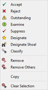
From this menu you can:
• Assign a new status to any point(s) highlighted in the Selection window
• Find and designate a point representing a shoal
• Change the classification setting of data formats that support classifications
• Remove points from the selection
• Remove all but the superselected point from the selection
• Copy the information about the selected point(s) to a text file
• Clear the selection
The flags in this menu are also available from the Tools > Editors > Subset menu or when right-clicking in the subset view windows. When accessed from the pop-up menus in the subset view windows, the flag will be applied to all selected points, where as the pop-up menu in the Selection window only applies the flag to the highlighted points.
3. Select the relevant flag.
Menu | Tools > Editors > Subset > flag |
Tool |
|
Pop-up | highlighted point > flag (Selection window) |
Pop-up | highlighted point > flag (Subset Editor -2D View / Subset Editor - 3D View windows) |
The status flag of the selected point is changed.
To change the status of several points in the Selection window, use the <Shift> or <Ctrl> keys while clicking to select all relevant points, then select the desired flag.
If the subset bounding box is moved or resized, or the editor is closed, you will be prompted to save your changes.
Designate
The Designated flag allows you to identify the shoalest point in a selected area. This flag is provided to ensure that the shoalest depths are maintained in charts and other standard hydrographic products. When running a process that uses data from an existing source to generate a new data source, designated points are often persisted in the output, or an option is provided to choose to include the designated points despite any suppression settings.
When designating points, it is possible to enter and save metadata for the selected points. In order to do this you must have the Prompt for designated attributes option enabled in the Coverage category in Tools > Options before beginning the designating process.
1. Select the shoalest point from a cluster of selected points.
2. Select the Designate command.
Menu | Tools > Editors > Subset > Designate |
Tool |
|
Pop-up | highlighted point > Designate (Selection window) |
Pop-up | highlighted point > Designate (Subset Editor -2D View / Subset Editor - 3D View windows) |
If the attributes option is enabled, the Designate Node dialog box is displayed and you must continue with the next step.
If the attributes option is not enabled, the point is flagged as designated and the task is complete.
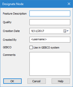
The fields in this dialog box are not mandatory. Information can be entered in each field as needed.
3. Enter a brief textual description for the selected point in Feature Description.
4. Enter a brief explanation as to the validity of the point and the security protections in Quality.
The Creation Date and Created By fields are both populated automatically, but can be changed if necessary.
• The Creation Date field identifies the date the point was designated or last modified.
• The Created By field identifies the user account name that was used to designate the point.
5. Change the values for Creation Date and Created By, if necessary.
6. Click the Use in GEBCO system check box if the selected data uses the GEBCO (General Bathymetric Chart of the Oceans) system.
7. Add any additional comments as needed.
8. Click OK.
The selected point is flagged as designated. When you close the Subset Editor, a message will be displayed asking if you would like to save the changes.
9. Click Yes to save the designated flag on the point.
A Designated layer is added to the Layers window. If a Designated layer already exists, the designated point is saved to that layer. Properties for this layer can be defined in the Properties window.
Find and Designate
This flag locates the shoalest point in a selected area. Similar to the Designate command, this command is provided to ensure that the shoalest depths are maintained in charts and other standard hydrographic products.
The Find and Designate command is also available when viewing 2D data in the Display window. See Designate Soundings for more information.
When designating points, it is possible to enter and save metadata for the selected points. In order to do this you must have the Prompt for designated attributes option enabled in the Coverage category in Tools > Options before beginning the designating process.
To find and designate a point:
1. Select the Find and Designate command.
Menu | Tools > Editors > Subset > Find and Designate |
Tool |
|
Pop-up | highlighted point > Designate Shoal (Selection window) |
Pop-up | highlighted point > Designate Shoal (Subset Editor -2D View / Subset Editor - 3D View windows) |
If the attributes option is enabled, the Designate Node dialog box is displayed and you must complete the appropriate fields before the points can be designated.See Designate for instructions on completing the fields.
If the attributes option is not enabled, the shoalest point is located and flagged as designated.
Auto-Cursor Mode
If setting status flags on a number of individual points, the auto-cursor mode tool can be useful. This tool allows you to select the status flag you want to assign to each point, and then simply click each of those points individually to apply the selected flag.
1. Select the Auto-Cursor Mode command.
Menu | Tools > Editors > Subset > Auto-Cursor Mode |
Tool |
|
2. Select the status flag that you want to assign.
3. Click each of the points to which you want to assign the status.
4. Select the Auto-Cursor Mode command again when finished.
All points selected while in auto-cursor mode were flagged with the selected status.
Select Isolated Points
Menu | Tools > Editors > Subset > Select Isolated Points |
Tool |
|
The Select Isolated Points command is used to identify and select isolated points in a point cloud subset. Isolated points are often noise in the data that can be rejected or suppressed. Points are identified as isolated based on the neighbouring points and sources within a specific area around the point. This method makes it possible to quickly identify, select and then flag several points.
There are three possible types of neighbours the application will look for when identifying isolated points:
• Nearby points: This type of search looks at the number of points within a specified area around the point being tested.
• Sources of nearby points: This type of search looks at the number of sources contributing to the points within the area around the point being tested.
• Both points and sources: This type of search looks at both the number of points around a point and the number of sources contributing to those neighbouring points.
The application checks for neighbouring points in a cylindrical space around each point in the subset. The size of the cylinder is defined by the user. All points found by the process are added to a selection that can then be used to flag the points.
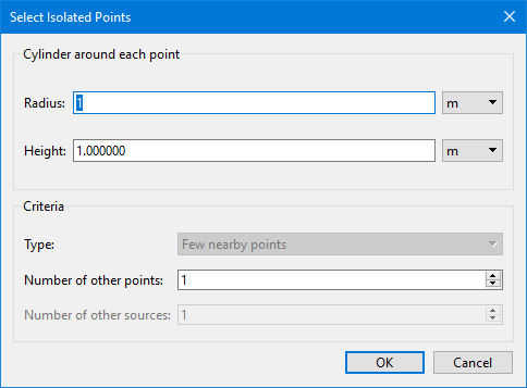
The Select Isolated Points command uses the following dialog box.
Option | Description |
|---|---|
Radius | The radius of the cylindrical search area. 1. Enter a value and select a unit of measure. |
Height | The height of the cylindrical search area. 1. Enter a value and select a unit of measure. |
Type | The type of search to perform when identifying isolated points. This field is only enabled if more than one point cloud is open in the application. If only one point cloud is open, Few nearby points is used by default. |
Number of other points | The minimum number of neighbouring points that must be present within the search cylinder surrounding the point being tested. If the number of points is not met, the point is selected. A minimum of 1 is used by default. This field is disabled if Type is set to Few sources of nearby points. |
Number of other sources | The minimum number of sources contributing to the points within the search cylinder surrounding the point being tested. If the number of sources is not met, the point is selected. A minimum of 1 is used by default. This field is disabled if Type is set to Few nearby points. |
To use this command:
1. Open the relevant point clouds.
2. Launch Subset Editor.
3. Select a subset in the 2D View.
4. Select the Select Isolated Points command.
5. Enter a Radius value and select the unit of measure for the cylinder.
6. Enter a Height value and select the unit of measure for the cylinder.
7. Select the Type of neighbours to search for.
8. Enter the number of points and/or sources that must be present for a point not to be selected as isolated.
9. Click OK.
The Selection window is populated with all points identified as isolated.
10. Select the points in the Selection window and apply the desired flag to the points.


