| Description | Example |
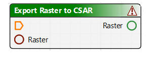
Process | A specific single tool type which performs a task with an output | An example of process: Export Raster to CSAR. |
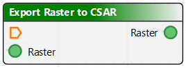
Tool | Tool is an all-encompassing term for all items in a model. Kinds of tools listed in the Tools window include: • a specific process applied to data, such as Export Raster to CSAR. • a function such as Exists (which verifies that a specific data set exists). Tools display validation icons. | Sample tool: The red icon with the exclamation point in the title bar indicates that the process is incomplete or parameters are not fully defined. Red circles indicate where parameters must be linked. Once defined or connected to a user parameter these are green-filled. Optional parameters are always green. |
Connection | A linkage point on a tool that links data to a particular parameter of a process, for example, input, output, condition and options. • An Input connection is used for data to which the process is applied, for example, the Raster input port points to the location of the data. • Output is what is produced by the process, for example, a CSAR surface. |
|
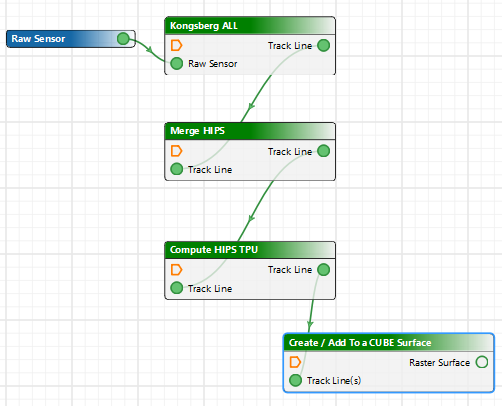
Connector | A line drawn from tool to tool to show how one function connects to the other. Connectors will not attach Input to Input or Output to output. | For example, a line from an output port labelled Track Line(s) to a Coverage input port which indicates the output data will contribute to the coverage. |
Model | A group of tools and their associated properties, linked in such a way to perform a task or a series of tasks in a workflow, which is saved as a *.processmodel file. | |
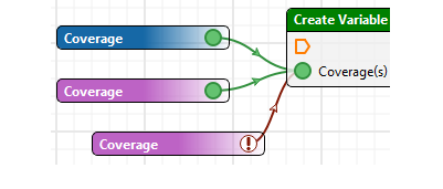
Parameter | Use a Parameter to set the requirement for a specific input value, to be set at the time the process model file is run. When the model file is run the Run dialog box will display a field so the user can identify the required input. This enables the process model file to be applied to different datasets. Users will be prompted to supply the required information when the model is run. Parameters are displayed in blue. |
The red icon (and red connector line) on the Value tool indicate that a value must be set in the Properties window. Once set, the icon turns green. See also Values and Parameters |
Value | Set a specific value that will allow the process model file to run. Value tools are displayed in purple. | |
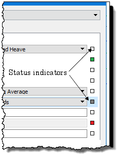
Properties Status Indicators | Fields in the Properties window for each process, parameter or value are set to default values. Status indicators are: • White: default value • Grey: indicates the field is no longer in the default state (a value has been entered, or the default value has changed). • Red: indicates the property is in an invalid state, such as an incorrect setting to a missing setting • Green: displays the property name as an input to the process. Defaults can be restored by clicking on the indicator box and selecting “Reset”. |
|