Menu | View > Pan > Terrain Flyer / First Person / Move View |
Tool |
|
Navigating in 3D is like flying through the terrain. You can do this using several methods, or combinations of methods. You can record the “flight” and save it to a video file. See 3D Flight Path for information on recording the flight.
Keyboard Shortcuts
You can navigate the 3D View using various keyboard shortcuts:
Key | Action |
|---|---|
W | Pan forward in a straight line, horizontal to the terrain. |
S | Pan backward in a straight line, horizontal to the terrain. |
C | Zoom into the display. |
V | Zoom out of the display. |
| Pan up in a straight line. |
| Pan down in a straight line. |
| Pan left in a straight line. |
| Pan right in a straight line. |
A combination of the keys can be used to move in non-linear directions.
When using the keyboard to navigate, the speed you travel through the display or pan the view varies based on the length of time that the key is pressed. The longer the key is pressed, the faster the view changes.
Mouse Controls
A variety of functionality is available using the mouse in the 3D View. Each mouse button provides a different functionality:
Mouse Button | Action |
|---|---|
Left | Select points at the current cursor location. Press and hold while dragging the cursor to create a bounding box and select a group of points. See Selecting Data for more information. |
Right | Activate the Control Axes used to rotate the view. See Control Axes for more information. |
Middle | Navigate the display relative to the direction of the mouse cursor. The actual direction moved will depend on the Controller Type selected. |
Middle (wheel) | Scroll forward to zoom into the display. |
Middle (wheel) | Scroll reverse to zoom out of the display. |
The functionality of the right mouse button and the middle mouse button can be swapped using the Swap ... Mouse Button option in the 3D category of Tools > Options. The options are:
• False, the default behaviour is used - the right mouse button provides the control axes functionality and the middle mouse button is used to navigate the view.
• True, the behaviour of the buttons is reversed - the middle mouse button provides the control axes and the right mouse button is used to navigate the view.
Menu | View > Pan > Terrain Flyer / First Person / Move View |
Tool |
|
When using the mouse to navigate, the speed you travel through the display or pan the view varies with the cursor’s distance from the centre (stationary) point. Also, the type of adjustment applied to the view when using the mouse differs based on the selected Controller Type. The Controller Type controls how movements of the mouse will adjust the display. The Controller Type setting is accessible from the View menu or the Standard toolbar. There are three possible settings for the Controller Type:
• Terrain Flyer (3D): When this option is selected, the view is adjusted from the perspective of the height source.
• First Person (3D): When this option is selected, the view is adjusted from a camera view of the current display.
• Move View (3D): When this option is selected, the display can be panned in any direction by pressing and holding the mouse button while dragging the cursor.
The Overview command can be used to return the display to the original state after the display has been adjusted. See Overview for more information.
Control Axes
Navigating with the mouse provides use of the control axes, which allows you to focus the view on a specific location of the view.
1. Move the cursor over the surface.
2. Press and hold the right mouse button.
The view re-centres on the selected location and a set of control axes are displayed as an overlay to the surface.
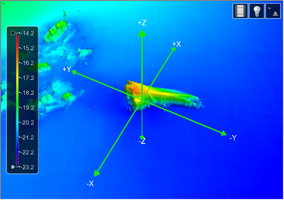
3. To rotate the view horizontally, move the mouse to the left or right.
4. To rotate the view vertically, move the mouse up or down.
5. Release the middle right button to hide the control axes.
Controller Panel
The Controller panel directional pad and slider controls are used to modify the view and perform a fly-through.
The Controller panel can be turned on or off using the Controller Panel option in the 3D options of the Display category in Tools > Options. This category also provides Speed options that allow you to control the speed with which the view is adjusted.
When turned on but not in use, the panel becomes transparent so as not to obstruct the view of the data. The Controller contains the following controls:
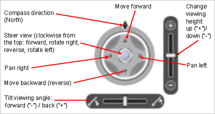
1. To pan the view, click the arrow for the direction in which you want to move. Clicking once will adjust the view slightly, clicking and holding the mouse button will continue to move the view until the mouse button is released.
2. To pan the view in a free motion, click and drag the steering ball in the middle of the panel. The view will pan in whichever direction the ball is moved. The further the ball is moved from the centre of the panel, the faster the view will be changed.
3. To change the viewing height or angle, slide the bar on the appropriate tool until the desired view is achieved.
As the view is changed with these tools, the Compass direction will change to indicate the direction in which the data is facing.
Navigation icon
To navigate using the navigation icon, you must have both the 3D and 2D view windows visible. The easiest way to do this is to use Tile Horizontally or Tile Vertically.
The navigation icon is displayed in the 2D window.
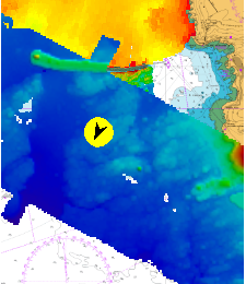
The direction of the arrow indicates the compass direction you are facing in the 3D view.
To rotate using this icon:
1. Click on one side of the icon.
The arrow on the icon rotates. The 3D View spins to match.
To navigate using this icon:
1. Press and hold the left mouse button and drag the cursor.
A dashed line extends from the icon.
2. Release the mouse button when the dashed line is pointing to the correct location.
The icon turns and moves to the new location and the 3D View shifts to match.
Selecting Data
If the data displayed in the 3D view is in the format of a raster surface, point cloud, variable resolution surface or TIN, it is possible to perform a selection. The selection is performed using the standard 2D view selection tools. Refer to the topics for the various Select commands for information on selecting features. The Selection window will be populated with the positions of the selected nodes and values for all bands in the coverage. The selection is made on the points that represent the primary Z band of the coverage. If there is no primary Z band, then the selection is made on the first elevation type band displayed in the 3D view. If no elevation type bands are displayed, then the Z positions of the first scalar band are used.


