You create a model diagram by adding tools to the model view then connecting them in the order in which they must be applied. The output of one tool is the input of the next tool or tools.
Add a tool to the model
To add a tool to the model view, do one of the following:
• drag the tool from the Tools window to the model view. You can drop the tool anywhere within the model view.
• double-click the tool in the Tools window: The tool will always be added in the centre of the model view window.
When the tool is selected, its options are displayed in the Properties window.
Connect tools
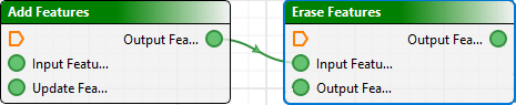
To connect tools:
1. Click on a connector on one tool and drag a line to connect it to a connector on the second tool.
A curved green line will follow the cursor.
2. Release the line over the connector on the second too.
It will attach itself to the second tool.
For example, connect an output connector on one tool to an input connector on another.
Move a tool
To move a tool around in the model view window:
1. Click on the title bar of the tool.
The cursor changes to a hand ( ) to indicate that the tool can be moved.
2. Drag the tool to the new location.
Any connecting lines will stretch or shrink as necessary to stay with the moved tool.
The tool always snaps to the underlying grid, to simplify organizing processes and other objects in complicated models.
Delete a tool
To delete a tool from the process model:
1. Select the tool.
A blue outline indicates that the tool is selected.
2. Select a Delete command.
Menu | Edit > Delete |
Pop-up | Delete |
key | Delete |
3. To confirm the deletion, click Yes.
The tool is removed.
Delete a connection
To delete a connection:
1. Click on the connecting line.
The line will turn blue.
2. Press Delete to remove the connector.
Tools can be connected to as many other tools as logic allows.