Menu | Tools > HIPS and SIPS > Georeference Bathymetry |
Tool |
|
Menu | Tools > HIPS and SIPS > Georeference Bathymetry |
Tool |
|
The default functionality of the Georeference Bathymetry process is to merge the HIPS data from time-based sensor data into processed geographically-referenced depth data. Input data is from one or more track lines. Output is a processed point cloud.
This process converts along track/across track depths in raw data into latitude, longitude, and depth by combining the ship navigation with the horizontal and vertical offsets from the HIPS vessel file. This geographically references the sounding position and depth.
All other functions for SVC, TPU computation or to apply a vertical adjustment using GPS height or tide from traditional or from zones, are optional.
Interface
These functions are applied using the Georeference Bathymetry dialog box.
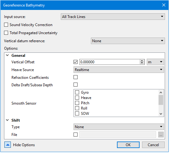
Input Source | This field displays: • “All Track Lines” if no track lines are selected (this is the default setting) • “Selected Track Lines” if some lines are selected, • names of layers or groups of track lines as selected by user |
Sound Velocity Correction | Enable the check box to apply SVC during Georeference Bathymetry process. This will display SVC options. |
Total Propagated Uncertainty | Enable the check box to apply TPU during Georeference Bathymetry process. This will display TPU options. |
Vertical datum reference | Select None, Tide or GPS. Default is None. |
Show Options | Click the down arrow to display the list of options. |
Procedure: Georeference all track lines
1. Open data.
2. Select the Georeference Bathymetry command from the Process menu or toolbar.
The Georeference Bathymetry dialog box is displayed. If no specific track lines have been selected, the Input source field displays “All Track Lines”.
3. Set options if desired. See Optional settings.
4. Click OK to apply the process.
All track lines in the data set will be georeferenced.
Procedure: Georeference a single line
To georeference a single line:
1. Select the line in the Layers window.
2. Select the Georeference Bathymetry command from the Process menu or toolbar.
The Input source field will display “Selected Track Lines”.
3. Continue as above.
Procedure: Georeference a subset of available lines
To georeference multiple lines from a larger set of lines, use the Group function to select the desired lines.
1. Open data.
2. Select the Group command from the right-click menu in the Layers window.
3. Name the group.
4. Select a track line and drag it into the named group. Repeat with the rest of the track lines to be merged.
5. Select the Georeference Bathymetry command.
6. Select the named group from the Input source drop-down list.
7. Continue with process.
Optional settings
To access the optional settings for the process:
1. Open data.
2. Select the Georeference Bathymetry command from the Process menu or toolbar.
3. To set SVC or TPU options, enable the Sound Velocity Correction and Total Propagated Uncertainty check boxes.
4. To set Vertical datum reference options, select the type of reference to be used (the default value is NONE):
• Select Tide to apply Observed tidal corrections (see Total Observations field in the following table)
• Select GPS to apply tidal corrections.(see GPS Vertical Adjustment field in the following table
Note: GPS Height and Model must be in the same coordinate reference system.
5. Click Show options.
The options fields are displayed. 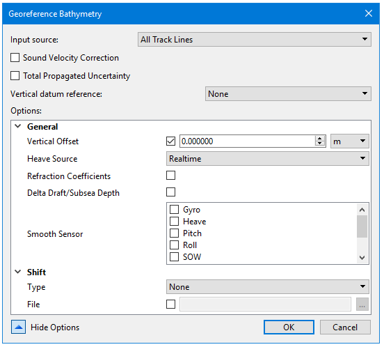
Option | Description |
|---|---|
General | |
Vertical Offset | Set a value for the static offset to be applied to the processed depths. Default units are set as metres, but this can be changed by selecting another unit type from the drop-down list. |
Heave Source | Select the type of heave to be applied |
Refraction Coefficients | Set the check box to apply coefficients. |
Delta Draft/ Subsea Depth | Set the check box to apply to the processed depths. |
Smooth Sensor | Select smoothing coefficients to apply to the selected data. |
Shift | |
Type | Apply beam shift to the processed depth solution from a beam look-up table. The beam shift look-up table consists of two columns, one contains the beam number and the other the value of the shift. Only the beams listed in the table will be shifted. For example: Beam number, Shift Value 1,2 2,2 3,2 22,3 75,1 The values can shift statically or by percentage of the water depth of the sounding being shifted. • None: No beam shift will be applied • Static: Static beam shifts will be applied - as a straight shift (positive down, depths get deeper) • Relative: Relative beam shifts will be applied as a percentage of the depth being shifted. The default value is None. |
File | Enable the check box and browse to the location of the beam shift file. |
Sound Velocity Correction | |
Sound Velocity Profile(s) (SVP) | Enable the check box and browse to the location of the file(s) or folder(s) containing the profiles. |
Profile Selection Method | Method for selection of which sound velocity profile to apply for each ping, when multiple profiles are available. From the drop-down list, select the method to be applied to each ping. • Previous in Time • Nearest in Time • Nearest in Distance • Nearest in Distance within Time • Use Last Method (the method applied when this option was chosen when georeferencing). The default value is Previous in Time |
Nearest in Distance Hours | Specify the number of hours used with the Nearest in Distance Within Time profile selection method. The default value is 1. |
Use Surface Sound Speed | Enable the check box to insert surface sound speed into the SVP used during sound velocity correction. When not available, SVP is used without any changes. |
Steered Beam Angle Recomputation | Enable the check box to perform an additional computation of the steered beam angles based on a new surface sound speed that will be interpolated from the sound velocity profile. This is only available when the Surface Sound Speed is applied. |
Total Propagated Uncertainly | |
Measured Tide | Select a number specifying the error value for the tide station, equivalent to the standard deviation of the tide gauge measurements. This is ignored if tide source is set to Realtime. The default value is 0. Default units set to metres. |
Tide Zoning | Select a number specifying the value for the vertical uncertainty in the range calculation for a tide zone file. The default value is 0. Change units by selecting from the drop-down list |
Measured Sound Velocity | Select a number specifying the value for the uncertainty of inaccuracies in SVP measurements. The default value is 0. Change units by selecting from the drop-down list: |
Surface Sound Velocity | Select a number specifying the surface offset value used to account for errors in surface sound speed measurements that alter the beam angle. (This parameter is only applicable to systems that require accurate surface sound speed measurements.) Change units by selecting from the drop-down list: |
Sweep Maximum Heave | Select a number specifying the maximum uncertainty value for the estimated observed heave of the transducer boom. The default value is 0. Change units by selecting from the drop-down list: |
Sweep Maximum Roll | Select a number specifying the maximum uncertainty value for the estimated observed roll of the transducer boom. default value is 0. Change units by selecting from the drop-down list: |
Sweep Maximum Pitch | Set a number to be the maximum uncertainty value for the estimated observed pitch of the transducer boom. The default value is 0. Change units by selecting from the drop-down list: |
Navigation Source | Set the source of the uncertainly values for Navigation: • Vessel (default) • Realtime |
Sonar Source | Set source of the uncertainly values for Sonar: • Vessel (default) • Realtime |
Gyro Source | Set the source of the uncertainly values for Gyro: • Vessel (default) • Realtime |
Pitch Source | Set the source of the uncertainly values for Pitch: • Vessel (default) • Realtime |
Roll Source | Set the source of the uncertainly values for Roll: • Vessel (default) • Realtime |
Heave Source | Set the source of the uncertainly values for Heave: • Vessel (default) • Realtime • Delayed |
Tide Source | Source of the uncertainly values for Tide: • Static (default) • Realtime |
Tidal Observations (for Vertical datum reference) | |
Tide File | Select the check box and browse to the location of the tide station or zone file to be used. |
Weighted Average | 1. Set so that the weighted average can be calculated during multiple tide station interpolation. |
Compute Errors | 1. Set so that errors can be computed during multiple tide station interpolation. |
GPS Vertical Adjustment (for Vertical datum reference) | |
Compute GPS vertical adjustment | If set, computes a vertical adjustment for the soundings using the ellipsoid as reference |
Model file | 1. Enable the check box and browse to the location of the datum model. The datum model can be one of type TIN, raster surface or point cloud. |
Band Name | Displays the datum model band name (applies to raster surface or point cloud in CSAR format. |
ASCII Format Information File | Displays the path to the file that describes the format of the input ASCII files. |
Coordinate Reference System | 1. Select check box to set CRS. |
Smooth GPS Height | 1. Set option to apply smoothing to GPS height. |
Output Components | Set the check box to create an ASCII text file (GPSTideComponents.txt) in the line folder with all the components extracted/interpolated during the Georeference Bathymetry process. |
