Menu | Tools > Automatic Boresight Calibration |
Automatic Boresight Calibration provides a systematic approach to calibration as an alternative to the traditional, manual patch test.
The boresight computation is applied to a set number of patches that are automatically created from planar areas of the sea-floor, using recursive division based on the density of soundings and whether or not the patch is selected for sensitivity to pitch, roll or yaw.
Boresight estimations for pitch, roll and yaw, with standard deviation values, are displayed in the dialog box, and can be saved directly to the HIPS Vessel file. A text report can also optionally be saved to a file.
GPS Height must be available in the imported data as the calibration calculation refers to computed sounding positions based on GPS X, Y, and Z. |
Data Selection
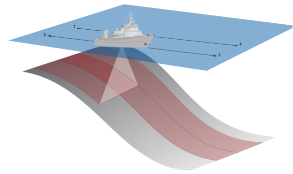
This calibration process requires line data that runs up and down a smooth, 10 degree minimum slope, such that the outer edges of one swath falls approximately at nadir for the adjacent run line. Put another way, it requires two reciprocating pairs of lines that run up and down a slope with 50% overlap.
An optimum line pattern is illustrated below, up and down the slope with the edge of each swath aligning roughly with the boresight position of the first line set.
This calibration process can benefit from using a surface with a root-mean-square (RMS) error layer to observe the improvement in values due to calibration, by comparing the RMS layers before and after calibration. See Calibration Workflow
Sound Velocity Correction must be applied to the data prior to calibration. For Kongsberg systems the sound velocity applied during acquisition is used by default and no further corrections are required in HIPS |
Interface
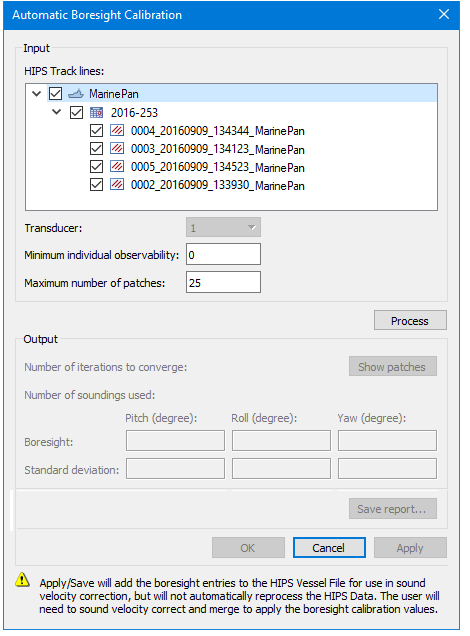
This automatic calibration tool is applied using the Automatic Boresight Calibration dialog box.
Option | Description |
Input | |
HIPS Track Lines | Displays the vessel name, day and lines of the selected project. 1. Select the specific vessel or individual lines to use in the boresight computation |
Transducer | (This option is disabled for single head data.) For dual-head data, the calibration process is run on one transducer head and saved to the HVF. Calibration is then run on data for the second head and this is saved to the HVF. 1. Use the Transducer field value to run calibration on one transducer, then the other. The default setting is transducer 1. Data must then have SVC and Merge applied again. |
Minimum individual observability | Minimum observability criteria for a given patch to be considered in the boresight computation. Changing this value to something larger than 0 may help limit the selection of undesirable patches for the boresight estimation. See also Observability. |
Maximum number of patches | The maximum number of patches which meet density and planarity criteria, to use for boresight computation. Increasing this value will increase processing time, but may yield better results when the survey pattern is not optimal, e.g., slope is less than 10 degrees. Default value is 25 patches. |
Process | 1. Click to run the calibration process. Once this is done, the button is labelled Reprocess, so that the boresight can be re-processed with new values if a change is made. |
Output | |
Show patches | Once processing is done, values are displayed in the dialog box, and this button is activated. 1. Click to display the observability patches. |
Number of iterations to converge: | Displays the number of times the process is applied to achieve the optimum match of density and |
Number of soundings used | Displays the number of soundings used in the process |
Boresight | Displays computed Pitch, Roll and Yaw calibration values and their associated standard deviation. |
Standard deviation | |
Save report... | Opens the Save Calibration report dialog box to save the calibration process results in text format. |
OK | Saves the calibration values to the SVP section of the HIPS Vessel File and closes the dialog box. (This does not update the HIPS data.) |
Cancel | Closes dialog box without applying calibration values to HVF data. |
Apply | Adds the calibration values to the HIPS Vessel File, for use in sound velocity correction. The dialog box open remains open. |
Both Save and Apply will add the boresight entries to the SVP section in the HIPS Vessel File but will not automatically reprocess the HIPS data. Sound velocity correction must be applied to the data and the data must then be merged to apply the boresight calibration values. | |
Procedure
1. Import, process and Merge data.
2. [Optional] Create a gridded surface from the data and add a RMS error layer. (See New Surface (Regular Gridded) and Compute Root Mean Square Error)
3. Select the project in the Project window.
4. Select the Automatic Boresight Calibration command.
In the Display window the cursor changes shape.
5. Click in the Display window, and drag the cursor to select the area of interest for calibration. Any data outside of this range will be ignored.
The Automatic Boresight Calibration dialog box is displayed.
6. Set Input options.
7. Click Process.
Boresight and associated standard deviation calibration values will be displayed in the table.
8. Click Show patches to view the observability patches for each boresight estimation or for combined observability.
The Observability graph window is displayed.
Observability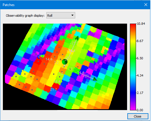
Use the drop list at the top of the dialog box to view the graphs for Pitch, Roll, and Yaw, and select Combined to see a graph that combines all three.
The colour legend at the right of the window shows the range of observability values. Higher values indicate better observability.
Patches displaying a solid dot indicate they were selected for use for the boresight estimation.
9. Click Reprocess to run calibration again with new settings.
10. If calibrating a dual-head system, select “2” from the Transducer field and repeat steps 7-9 for the second transducer.
11. Click Save report to create a file containing a text version of the process results, e.g. the number of iterations needed to converge, the number of selected soundings and the boresight estimation results
12. Click OK to apply the adjustments to the SVP section of the HIPS Vessel file and close the dialog box.
13. Apply SVC to data.
14. Merge data.
15. [Optional] Create a gridded surface from the data and add a RMS error layer. Compare to previous surface.
16. Repeat the process with new values if necessary.