Menu | Tools > Surfaces > Vertical Shift |
Pop-up | Vertical Shift |
Apply a vertical shift to one or more layers (Depth, Height, etc.) of an existing surface or point cloud, to create an output surface with an increased or decreased Z value. This function is not only applied to update data, it may also be used to apply tide.
These shift types are available, depending on your configuration:
• ASCII File shift: apply a file containing a grid of sounding datum heights, see ASCII File Shift
• Raster: apply a shift to a coverage using a raster surface. See Raster Shift
• Value: shift the entire surface by a single value, see Single Value Shift
• Tide File: apply tide correction using data from a single station or multiple stations, see Tide File Shift
The shift types are explained below, followed by the procedure for performing a shift.
With all shift types, you have the option of applying a vertical coordinate reference system to the output. The vertical component is added to the metadata of the surface, but does not apply any vertical transformations. The options available in the list are controlled by the vertical CRS database. This list can be edited using the Vertical Reference System Editor. For more information, see Vertical Reference System.
ASCII File Shift
The ASCII file option uses a file containing points that represent a boundary around the entire surface, or the section of the surface you wish to shift. Using this boundary, a TIN will be calculated according to the values in the ASCII file. These values will then be applied to the values in the area of the surface encompassed by the boundary.
If using an ASCII datum model file, the file must follow a specific format:
• The data must be in comma delimited format.
• The coordinate type must be Geographic and the format must be decimal degrees (Latitude, Longitude, Z).
• The hyphen symbol (-) must be used to designate coordinates in the Southern or Western hemispheres
An example of an ASCII shift file is shown below:
-33.848326,151.192435,10.4
-33.849484,151.192370,10.1
-33.849237,151.193173,9.7
-33.849506,151.194227,9.8
-33.848298,151.193916,10.0
-33.848402,151.193149,10.2
Values in the ASCII file are always Z positive down by design. If your ASCII file contains negative values, this will be reflected in the resulting shift values. For example, a file with a value of -10 applied to a surface that is positive down with a depth of 20m, would result in a depth of 10m. If you were to apply that same file to a surface that is positive up, the result would be a height of 30m.
Using the example above, the following table shows what the resulting values would be with a given set of original values:
Original Value | Shift Value | Resulting Value |
8.2 | 10.4 | 18.6 |
8.6 | 10.1 | 18.7 |
7.3 | 9.7 | 17.0 |
7.4 | 9.8 | 17.1 |
9.1 | 10.0 | 19.1 |
9.2 | 10.2 | 19.4 |
Raster Shift
The elevation values in a raster surface band can be used to apply a vertical shift to the values in another coverage. Shift values can be applied to a single elevation band, for example the Depth band, or to multiple elevation bands, such as Depth, Deep and Shoal bands.
Tide File Shift
Tide data is used to generate final depths relative to tide datum by subtracting the tide from the sounding depth. This correction provides a more accurate depth value for the surface. When available, tide correction should be applied to all surfaces before using them to create charts.
Observations are loaded from a tide file (.tid) or from a zone definition file (.zdf). See Tide File Formats for full descriptions of these files.
• Tide files contain observations from a single tide station. Applying this file will apply tide observations for the surface for the specified time period. Tide files can be created or edited in a text editor. This type of tide file would be used if the surface falls entirely within a single tide zone.
• Zone definition files contain data that defines tide zones. Applying this file tells the application where the zones are and in turn, which observations to apply for your surface. Zone definition files are in ASCII format and can be edited in a text editor. This type of file would be used if your surface spans multiple tide zones.
Tide zones are closed polygons with tide, time and range corrections for a primary station, plus up to three backup secondary tide stations. |
Tide values for a particular area differ depending on the time of year and the time of day. You will need to specify the date and time of the data to apply when performing this type of shift.
Single Value Shift
A surface or coverage can be shifted by a single value. If you select this option, the value you enter in the Shift value field is used to shift the selected layers. The direction of the shift depends on the current application settings for the Z-axis Convention attribute.
For example, if the elevation is 12 metres below the datum and a shift of (positive) 10 metres is applied:
• if the Z-axis Convention is set to “Down is positive,” the result is 22 metres below the datum.
• if the Z-axis Convention is set to “Up is positive,” the result is 2 metres below the datum.
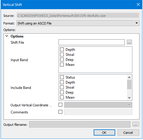
Interface
The Vertical Shift command uses the Vertical Shift dialog box.
This dialog box defines the attribute layers you want shifted and the amount by which to shift them. The resulting surface will contain all of the same layers as the source surface, but only those selected for shift will have their values shifted.
Any layer with a Z value can be shifted.
If the source surface contains a computed layer, that layer will lose its dynamic status and will no longer be affected by changes to the primary elevation layer. |
Option | Description |
Source | The input data for the process. The Source is defined by the coverage that was selected at the time the command was initiated. This field cannot be changed. |
Format | The type of shift to be applied. |
Options | The options for the selected shift type. The available options will differ based on the selection in the Format drop-down list. If you hover the mouse cursor over the name of an option, a brief description of the option is displayed in a tooltip. |
Output file name | The name and location for the output coverage file. |
Procedure
1. Select the source coverage in the Layers window.
2. Select the Vertical Shift command.
The Vertical Shift dialog box is displayed.
3. Select the Format of the shift type to be applied.
4. Define the necessary Options for the selected format.
5. Click the browse button (...) to define a name and location for the output surface.
6. Click OK.
A new coverage is created with the selected shift applied to the source data.