Menu | Tools > Limits and Boundaries > Envelope of Arcs |
Tool |
|
Menu | Tools > Limits and Boundaries > Envelope of Arcs |
Tool |
|
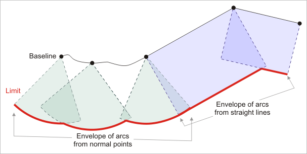
Calculate a limit line at a specified geodetic distance from a baseline.
According to the United Nations Convention on the Law of the Sea (UNCLOS), maritime limits can be calculated from normal points or from straight baselines.
The Envelope of Arcs command works on the entire contents of a layer or on a selection or superselection. When not using a selection, it is recommended that you either copy the baseline to a scratch layer or create a filter based on the unique identifiers of the selected objects before using the command.
Use the Interactive Baseline and Wagon Wheel Filter commands to create the baseline from an existing coastline or low water line.
Interface
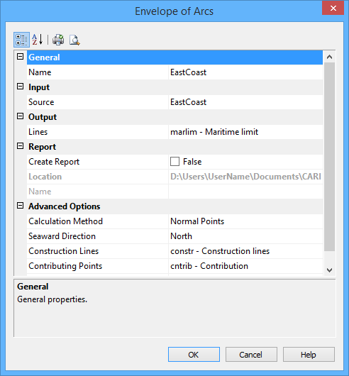
The Envelope of Arcs command uses the following dialog box.
Group | Property | Description |
General | Name | The name of the layer that will contain the new line. Select from the list. This can be the same as the source layer. |
Input | Source | The name of the layer that contains the baseline. Select from the list. |
Output | Lines | The feature acronym and attributes of the output line. Type an acronym directly or select an option from the list. The list contains the following options: • A list of recent objects, if any: Select this to reuse a previous object. • Template: Select this to define the feature acronym and attributes using a predefined template. This will launch the Select Template dialog box, from which you select a template, if any are available. • Objects: Select this to launch the Select Object dialog box from which you can manually select an acronym and define the attribute values. |
Report | Create Report | Select this option to generate a report of the start and end points of each arc along with the contributing points. |
Location | The location in which to create the report file. By default, the report is saved in the folder: This can be changed by clicking the Browse button (...) and selecting a new location. This location will be remembered the next time the tool is launched. | |
Name | The name to assign to the report. | |
Advanced Options | Calculation Method | Select from: • Normal Points: Use this if the baseline is formed of normal baseline points. The data is always interpreted as points, even if you select a line. In this case, only the vertices of the lines will be considered. • Straight Lines: Use this if the baseline is represented by straight lines. The line data is always interpreted as connected geodesics. The geodesic segments between the turning points of the baseline as well as these turning points are used in the calculation. |
Seaward Direction | The direction from the baseline where the arcs are to be drawn. Select from north, south, east or west. | |
Construction Lines | Draw the construction lines joining the end points of arcs on the limit line to their contributing points on the baseline. Type an acronym directly or select from the list. The list contains the following options: • A list of recent objects, if any: Select this to reuse a previous object. • Template: Select a template using the Select Template dialog box. • Objects: Define the feature acronym and attributes using the Select Object dialog box. | |
Contributing Points | Draw the contributing points using a specific object acronym representation. Type an acronym directly or select an option from the list. The list contains the following options: • A list of recent objects, if any: Select this to reuse a previous object. • Template: Select a template using the Select Template dialog box. • Objects: Define the feature acronym and attributes using the Select Object dialog box. | |
Limit | The geodetic distance of the limit being calculated from its baseline. Units are taken from the Distance setting in the Display Units Options tab. | |
Interpolation Interval | The interval between points on the output line. Type a value. When the value is 0, the interpolation interval value along the arc is automatically calculated as follows: • Up to 57 nautical miles: ~1/60th of the value of the limit distance • At and beyond 57 nautical miles: 1 nautical mile |
Procedure
1. Select the Envelope of Arcs command.
The default values for these settings are displayed using the Display Units settings in Options. |
The Envelope of Arcs dialog box is displayed.
2. Set any necessary options.
3. Click OK.
The limit line is drawn.
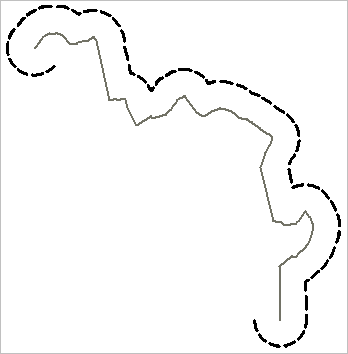
The limit line is created around the end points of the lines with a semicircle at the specified distance from the base point. A vertex in the semicircle is generally added at each one degree of arc. If that would result in subsequent vertices that are more than one nautical mile (1,852 metres) apart, a constant spacing of one nautical mile is used instead. If it would result in vertices closer than ten times the map resolution, then ten times the map resolution is used instead.
