Menu | Tools > Surfaces > By Pointing |
Tool |
|
Menu | Tools > Surfaces > By Pointing |
Tool |
|
Interpolation fills empty nodes in a grid using values from surrounding populated nodes.
The Interpolate by Pointing command allows you to manually interpolate each individual hole in a surface. This command can be repeated as many times as needed, altering the interpolation criteria for each hole if desired. All selected holes must be completely within the view extents in order for them to be filled.
When a hole is selected for interpolation using this command, the process begins by classifying all nodes in the surface as data, holes, or no-data (areas beyond the surface data but within the extents of the surface). The classification information is saved to a temporary Holidays layer. This is done entirely in the background and will not be visible in the application.
The classifications for the nodes are then used to interpolate each hole as it is selected, based on the user-specified criteria. If a hole cannot be completely filled, any changes that may have been applied to that hole will be reverted and a message will be displayed in the Output window.
This interpolation method implements changes on the selected source surface. These changes cannot be reverted using the Undo command; it is recommended that you back up your data prior to running the interpolation.
Related commands:
• Interpolate Surface By Range
Interface
The Interpolate by Pointing command uses the following dialog box.
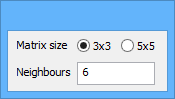
Option | Description |
Matrix size | The number of nodes surrounding a hole that will be analyzed for populated values. The options are 3x3 or 5x5, meaning the application will analyze a square area around each pixel of the hole that is either 3 pixels high and 3 pixels wide, or 5 pixels high and 5 pixels wide. |
Neighbours | The number of pixels within the matrix area that must contain data in order for the hole to be interpolated. For example, if you select the 3x3 matrix size option and enter a neighbours value of 6, that area must have at least 6 populated data nodes in order for a pixel in the hole to be interpolated. If there are not enough populated nodes present in the matrix area, it is possible that only some pixels in the hole will be interpolated or the hole will be skipped entirely by the process. |
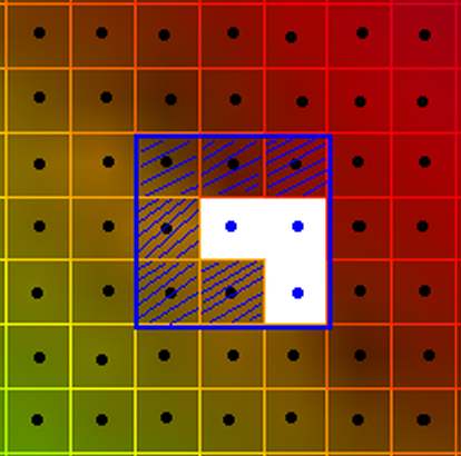
In the image below, the blue square represents a 3x3 matrix area. Each dot within the square is a node. Of those nodes, only the 6 shaded nodes contain data.
If the Neighbours field is defined as 6 or less, this would be sufficient to interpolate the pixel at the centre of the square. If the square were shifted to centre on each pixel in the hole, you can see the entire hole could be interpolated using the specified criteria.
Procedure
1. Select the root layer of the surface containing the holes to be interpolated.
2. Select the Interpolate By Pointing command.
A dialog box is displayed to define the interpolation settings and the cursor changes to indicate the interpolation method.
3. Select a Matrix size option.
4. Type a value in the Neighbours field.
The values entered for Matrix size and Neighbours will be remembered the next time the command is run. |
5. Click a hole to perform interpolation.
The process performs as many iterations as needed to fill the selected hole and flags those nodes as interpolated. A Depth Interpolated layer is added to the surface. This layer can be used to identify the interpolated data.
This command will remain selected and active until:
• the command is manually toggled off,
• another command is selected, or
• another layer is selected.
6. [Optional] Continue clicking to interpolate any remaining holes in the surface.
If further interpolation is performed on the surface, the existing Interpolation layer will be updated rather than creating another layer.
7. Turn off the Interpolation command.
