Menu | Process > Compute GPS Tide |
The Compute GPS (Global Positioning System) Tide function provides an alternative to normal tidal observation for reducing soundings to the sounding datum. A single sounding datum height, or a datum model file with a grid of datum heights, can be applied with the GPS height during the computation.
Any open surface layer or TIN layer can be selected as the input “model” for computing GPS tide. For details on sounding datum models and a sample *.info file, see GPS Tide format and INFO file.
You can open and view the GPS tide data in the Attitude Editor (Attitude Editor).
Sounding datum model files in gridded binary (.bin) or ASCII (.xyz) format can be opened in HIPS and SIPS as background data.
Interface
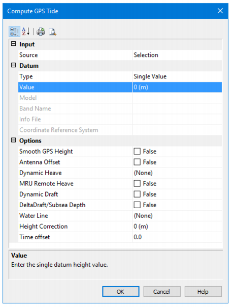
The Compute GPS Tide dialog box is used for computing GPS tide.
Option | Description |
Input | |
Source | Select “All Track Lines” to use data from the entire project and not just to the selected lines. |
Datum | |
Type | Select either Single Value or Datum Model as the type of datum to be applied. |
Value | If Single Value is selected as Type, enter a single datum height value in the Value field to apply a single distance from the ellipsoid to the antenna. |
Model | If Datum Model is selected as Type, use the drop-down list to select a currently open surface, or to select <Browse> and open a model file. The Model field will display the surface name, or the file name of the model file. |
Band Name | When a surface is selected in Type field to be used as the datum model, a elevation attribute must be selected in the Band Name field. |
Info File | When an ASCII file that can be parsed is used as the datum model, but is not recognized as a known format, you must also open a *.info file that will control the parsing of the ASCII data. As well, a coordinate system must be selected. This field is disabled if the selected file is a known format with an available info file (which will be applied by default) |
Coordinate Reference System | 1. Click the Browse button to open the Select Projection dialog box and set the relevant projection. |
Options | |
Smooth GPS Height | 1. Set to “True” to apply smoothing to GPS height. |
Antenna Offset | 1. Set to “True” to apply an offset of the GPS antenna from the reference point. |
Dynamic Heave | 1. Set to “True” to apply dynamic heave (either regular vessel heave, or delayed heave, if it exists). |
MRU Remote Heave | 1. Set to “True” to apply remote heave resulting from vessel roll/pitch on an offset-mounted MRU. |
Dynamic Draft | 1. Set to “True” to apply dynamic draft (as a result of interpolating the draft table in the HIPS Vessel File (HVF), or as stored in HIPS as time series data). |
Delta Draft / Subsea Depth (vehicle depth) | By default, Dynamic Draft (if available) is always applied if the option is set in the HIPS Vessel file. If the Delta Draft option check box is selected, Delta Draft (if available) is applied in addition to Dynamic Draft rather than being applied instead. 1. Select the Delta Draft / Subsea Draft check box to apply available Delta draft data. |
Water Line | 1. Select Vessel to apply the waterline offset set in the HIPS Vessel file, or select Realtime to apply real time data from the |
Height Correction | 1. Type a value to be used as a static offset for the GPS antenna. By default the units are set to metres. |
Time Offset | 1. Type a value in seconds to be applied as a time offset. |
Procedure
1. Select one or more track lines.
2. Select the Compute GPS Tide command.
3. Enter values for
4. Click OK to apply.
The GPS Tide is calculated for the selected line(s).
The settings in the dialog box are saved in a GPS Tide file in the line directory.