CARIS applications are built on a basic viewer for displaying read-only raster and vector data. Application functionality is accessed through modules that create and edit a wide range of products, including nautical charts.
Application modules require licenses but others are unlicensed. Some modules can be activated once an application module is activated.
Any of the following modules can be available depending on the installation.
Module | License | Description |
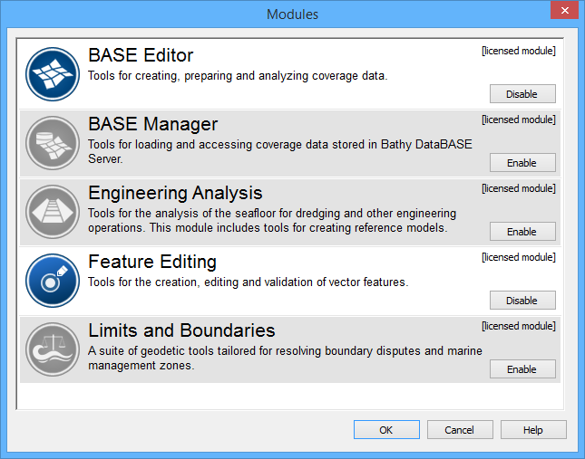
BASE Editor™ | Yes | Tools for creating, preparing and analyzing coverage data. |
BASE Manager™ | Yes | Tools for loading and accessing coverage data that is stored in a Bathy Database Server. |
Compose™ | Yes | Tools for creating, updating, validating and exporting S-57 and S-100 datasets |
Engineering Analysis™ | Yes | Tools for the analysis of the sea floor for dredging and other engineering operations. The module also includes tools for creating reference models. |
Feature Editing | Yes | Tools for the creation, editing and validation of vector features. This module is automatically activated when the BASE Editor and Limits and Boundaries modules are activated. |
HIPS1 | Yes | Bathymetry and water column processing tools for review, correction, and production of sounding data. |
Limits and Boundaries™ | Yes | Geodetic tools for resolving boundary disputes and marine management zones. |
SIPS2 | Yes | Sonar imagery processing tools to create high-resolution images from raw sonar data and to identify contacts within that imagery. |
SPINE | No | Tool to apply water level forecasts based on calculations from the SPINE web service. |
1 This term is a trademark of Teledyne CARIS, Reg. USPTO.
2 This term is a trademark of Teledyne CARIS, Reg. USPTO.
Modules are activated through the Modules dialog box.
After a license is acquired, a module can become enabled. When a module is enabled, commands and windows related to that module are made available in the application.
Both the basic CARIS application and modules share common files in C:\Program Files\CARIS\<application>\<version>\system. These files control what types of data can be opened and how that data is displayed.
In addition to the System folder, each module also has support files required by that module, to display and process data. The paths for module-specific files are
C:\Program Files\CARIS\<application>\<version>\modules\
<module name>\support
Specific system and module-support files are listed in the Options dialog box.
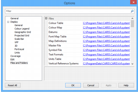
The information in default files can be extended with user-defined custom files that can contain additional information. The application can then be pointed to these custom files.
System and module support files must never be directly modified. Copy these files to another location and modify the copies. Then, point the application to these files through the Options dialog box or environment file. For more information on modifying default settings, see Environment Settings |
The following table lists files or folders that can be copied and customized with new or extended information.
Files/Folder | Component | Description |
Catalogue control file | System | The catalogue control file lists products along with the dictionaries and profiles that are associated with each product. This file can be revised or additional information can be added to it. The It is also possible to create custom catalogue control files and specify their location in the Files and Folders category of Tools > Options. See Catalogues for more information. |
Portrayal control file | System | The portrayal control file lists various portrayals along with files that make up each portrayal. Portrayals control how features are displayed. This file can be revised or additional information can be added to it. The default file is For more information about the portrayal control file, see Portrayals. For more information about portrayal files. see Portrayal Files |
Coordinate reference system | System | Files that define the coordinate reference systems. These also include datums and ellipsoids. For more information on these files, see Coordinate Reference Systems |
Elevation lookup | Modules | The elevationlookup.xml file tells the application which attributes to consider when populating Z values for features. The file lists common object acronyms that require a Z value and identifies the elevation attribute for each object. A shift value can also be specified for each object acronym. Defining this value will cause a vertical shift to be applied to the objects when they are loaded. The file is located in |
Resolution | Modules | The resolution.xml file controls the values that are populated in the X/Y and Z resolution fields of the New Feature Layer tool. A different set of values is provided for each layer type available. When a layer type is selected, the resolution values displayed will be assigned to the new layer. By default, X/Y values are defined in decimal degrees and Z values are defined in metres. If you require additional resolution values, you can edit this file to include a custom layer type and associated resolution values. The next time you open the application, your entry will be available as a layer type with resolution values you specified. The file is located in |
Units table | System | The unitstable.xml file defines the units of measure that are available in the application. Three different measurement systems are provided: • Metric System • British Imperial • US Imperial For each measurement system provided, the types of measurements, such as speed and area, are defined with keys and names, as well as attributes. Within each measurement type, the supported units are defined by Unit Key, Name, Label, a/b, and Precision. You can edit this file to add support for additional units of measure if necessary. The file is located in |
Utilities | System | The Utilities folder contains |
Validation | Modules | The Validation folder contains quality control files for checking data structure and logical consistency in S-57, VPF, and geometric data. Tests can be developed for additional file types. Default files are found in
Note that the quality assurance tests for each module are different. For more information on quality control files, see Quality Control |
Rules | Modules | The Rules folder contains mapping files to convert formats (e.g. GML to ENC) or to convert features (SLCON line features from LNDARE edges). Default files are found in
Note that mapping files for each module are different. For more information on mapping, see Mapping |
Product information files | Modules | The Default files are located in
For more information on product information files, see individual module support file guides. |
Attribute Filter Rules | System | The Attribute Filter Rules folder is the default location for all rule filter files that have been created and exported from a CARIS application using the Rule Wizard. The location for this folder can be changed using the Attribute Filter Rules option in Tools > Options. |