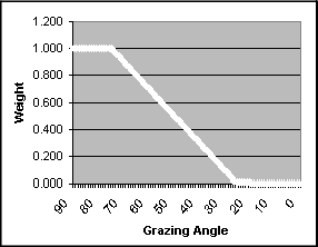
In this method of creating a gridded surface, the weight that a sounding contributes to the surface varies with the grazing angle of the sounding with the seabed.
This weighting value is important in areas with adjacent or overlapping track lines. The swath angle weight ensures that higher weight is given to beams from the inner part of a swath than to outer beams from adjacent track lines.
In this graph, beams with a grazing angle between 90 and 75 degrees are given a weight of 1.0. The weight decreases linearly to 0.01 as the angle with the sea floor decreases to 15 degrees.
This is the default swath angle weighting scheme defined in the file C:\Program Files\CARIS\HIPS and SIPS\<version>\modules\HIPS Essential\support\grazingangleweights.txt. To use another weighting scheme, customize this file.
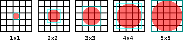
Maximum footprint
Swath Angle Weighting also will not apply a sounding to a node if the calculated footprint for the sounding is larger than the given maximum footprint.
The maximum footprint is given as the diameter of a circle centred on the sounding. The maximum footprint must be a positive integer and is set in raster resolution units. For example, if the maximum footprint is set to 4 and the raster resolution is set to 2 metres, then the maximum footprint size is a 8-metre circle contained in a 8×8-metre set of raster cells.
The figure below shows the sizes of various maximum footprints as they would appear on the pixel grid. The sounding will only be applied to pixels that are within the red circle.
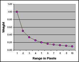
Range weighting
Range weighting is used in the creation of Swath Angle and Uncertainty surfaces to determine how a sounding value is applied to a node.
The range weight is inversely proportional to distance from the node: soundings closer to a node are given a greater weight than soundings further away. The calculated node positions are determined using the lower left corner of the area defined in the create Surface Wizard.
The number of nodes each sounding is applied to is determined by the size of the beam footprint. The beam footprint is calculated using depth, sonar beam width, and the grazing angle.
The sonar that is used, with the appropriate beam width, is defined in the Surface wizard.
A list of multibeam systems and corresponding beam widths is listed in C:\Program Files\CARIS\HIPS and SIPS\<version>\modules\HIPS Essential\support\devicemodels.xml.
The following graph demonstrates range weighting using distance from a node in units of pixels (multiples of the surface resolution).