The Corrections layer for a HIPS dataset, in the Layers window, contains corrections that have been set by a user in the Subset Editor Corrections. When the Subset Editor is closed, this layer can be used to select, query and delete the corrections on the track lines. Selecting the Corrections node in the Subset Control window will display the properties for Manual (2D Slice) or Automatic (Subset/View) depth and sound velocity (refraction) corrections.
The Corrections properties can be used to apply a change to the depths or to remove refraction artifacts which may exist after incorrect or insufficient sound velocity (SV) profiles are applied in either the acquisition or post-processing phase.
Corrections can be done using a manual process or an automated process.
• For manual corrections:
• A depth correction is done by setting a positive/negative value to change the depth at the top profile in the 2D slice of the currently loaded subset.
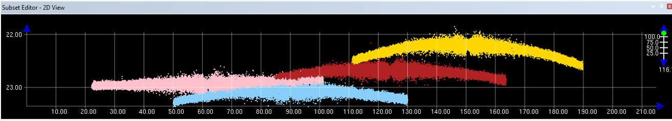
• A sound velocity correction is done by setting a positive/negative value to change the sound velocity at an automatically computed depth, half the shoalest depth in the subset. This change will remove the characteristic curved (upward or downward) refraction artifact. As the values are adjusted, the shape of the profiles will be changed in the Subset 2D View display.
• For automatic corrections, the process can calculate depth or sound velocity corrections, or both at the same time. To do this, a variety of settings are specified and the application uses those settings to calculate the corrections and apply them to the data over multiple iterations.
For sound velocity corrections, both manual and automatic, slower speeds result in shorter distances travelled for the same time period. This effect is more exaggerated in outer beams due to greater influence of ray-bending/refraction.
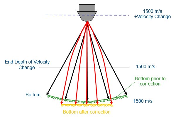
For correction purposes, a constant sound velocity (SV) is assumed. This constant is assumed to be 1500m/s and matching travel-times are calculated to represent the same bottom that the sound velocity profile (SVP) represented. The Sound velocity offset Depth is the depth at which the velocity will be 1500m/s again. The sound velocity correction is the amount the velocity will change between the water surface and the given depth.
A positive correction at the given depth will result in a flat bottom. This correction results in an upward ray deflection and an increase in distance travelled.
When a correction is added in the 2D slice, dynamic correction values are placed at the profiles along the edges of the subset extents for each track line. If there are no other corrections between the specified value and the edge of the Subset, a Subset Extent correction will dynamically change to an interpolated value between corrections. Also, Line Extent corrections will automatically be added to the track line at both ends, matching the value of the correction nearest each end. Multiple corrections can be added to a track line within a subset or by moving the subset and adding corrections in the new subset location. Each time that additional corrections are applied, the dynamic corrections closest to the newly added correction will be re-interpolated using the value of the latest correction.
Manual Corrections
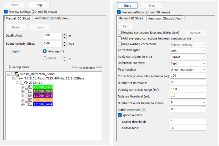
The Manual correction controls are described in the table below.
The previously selected tab will be remembered when the Corrections node is opened and will default to that tab. Any settings entered will also be remembered for subsequent uses. |
Property | Description |
|---|---|
Start/Stop | The Start and Stop buttons are used to enable or disable corrections mode. In order to apply corrections to a track line, the Start button must be used to enable corrections mode. The Stop button is used to disable corrections mode. If the Stop button is clicked after corrections have been applied, but not saved, a message is displayed asking whether changes should be saved, saved and Georeference Bathymetry run on the track lines, or discarded completely. Note: Corrections are not applied to the data until Georeference Bathymetry has been run. If the corrections are saved, but the process has not run, it will need to be run manually to apply the corrections. |
Preview settings (2D and 3D views) | Enable this option to view the effects of the correction values on the track lines in the Subset 2D View and 3D View windows. As the correction values are adjusted, the data in the 2D slice of the subset will be shifted according to the correction values. The preview includes all lines selected in the track lines list. |
Reset | The Reset button reverts any corrections that have been applied but not saved. If no corrections have been saved, all corrections will be reverted and the track lines will be returned to their previous state. If some corrections have been saved, only the unsaved corrections will be reverted. |
Save | The Save button is used to save any corrections that have been applied to the track lines. This changes all dynamic corrections to attributes on the track lines. |
Depth offset | This property is used to apply a depth correction for the currently selected track line. As a depth value is selected, the data is shifted according to the selected value. The initial value of control is set to an interpolated value at that location based on the last and next corrections. If it cannot interpolate, or no corrections have been applied, the default is 0. Click the Up or Down Arrow buttons to increase or decrease the depth value by which the data will be shifted, or type a value in the field. This value will be retained if another track line is selected, but the corrections have not been saved. |
Sound velocity offset | This property is used to apply a sound velocity (refraction) correction for the currently selected track line. Click the Up or Down Arrow buttons to increase or decrease the value by which the data will be shifted, or type a value in the field. This value will be retained if another track line is selected, but the corrections have not been saved. |
Depth | The depth at which to apply sound velocity offset corrections. This can be specified as either: • The average value of the surrounding soundings. • A specific value. |
Overlap slices | This option will turn off the overlap setting (which defaults to 20%) and each slice will move to cover new ground and not overlap the previous corrections. |
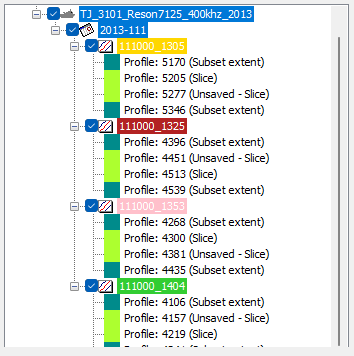
Track lines list | A list of visible track lines currently open in Subset Editor. This list is used to select the track line(s) to which corrections will be added. If the check box for a track line is not set, no corrections will be added for that track line for the subset being used. When the corrections are applied by running Georeference Bathymetry in Subset Editor, all track lines in the subset are processed, regardless of which track lines are selected in this control. If corrections have already been added to the data, this list can also be used to edit or delete existing corrections. Existing corrections will display in the list under the track line that has the correction(s), ordered numerically according to the profile numbers for which the corrections were created. Individual track lines can be expanded by clicking the + symbol beside the track line in the list. Alternatively, all track lines can be expanded at once by right-clicking on the list and choosing Expand All. The corrections will be labelled according to their status (Saved, Unsaved) and type (Subset extent, Slice, Automatic).
Note: Because subset extent corrections are not fixed values, they are not included in the list until the corrections for the subset are saved manually. Line extent corrections are never shown in the list since they always extrapolate and are never a fixed value. The label above the list will change depending on the current selection in the list. • If no track lines or corrections are selected, it will read “No selection”. • If one or more track lines is selected, it will read “Add/edit slice correction(s)”. • If one or more corrections is selected, it will read “Edit selected correction(s)” To select a track line, click the check box beside the track line name. To select a correction, expand the track line and click on the correction. To select multiple corrections, press and hold the <Ctrl> or <Shift> key while clicking on the corrections. When a correction is selected, the Depth offset and Sound velocity offset values of the correction will be displayed in the properties. If multiple corrections are selected these values will be blank unless all corrections have the same values. The offsets can be adjusted as needed to edit the corrections. If multiple corrections are selected, changing the offsets will apply to all corrections. Right-clicking a selected correction displays a context menu with a Delete command. This can be used to delete one or more corrections. Deleting a correction will automatically cause the line and subset extent corrections to be recalculated accordingly. To edit or delete a correction: 1. Place the subset in the area of the corrections to be edited. 2. Select the Manual (2D Slice) tab in the Corrections node. 3. Click Start. 4. Expand the track lines in the track line list and select the correction(s) to be edited. 5. To edit the correction, adjust the offset values as needed. 6. To delete the correction, right-click and select Delete. 7. Click Stop when finished editing and save the changes. |
Automatic Corrections
The Automatic correction controls are described in the table below.
The previously selected tab will be remembered when the Corrections node is opened and will default to that tab. Any settings entered will also be remembered for subsequent uses. |
Property | Description |
|---|---|
Start/Stop | The Start and Stop buttons are used to enable or disable corrections mode. In order to apply corrections to a track line, the Start button must be used to enable corrections mode. The Stop button is used to disable corrections mode. If the Stop button is clicked after corrections have been applied, but not saved, a message is displayed asking whether changes should be saved, saved and Georeference Bathymetry run on the track lines, or discarded completely. Note: Corrections are not applied to the data until Georeference Bathymetry has been run. If the corrections are saved, but the process has not run, it will need to be run manually to apply the corrections. |
Preview settings (2D and 3D views) | Enable this option to view the effects of the correction values on the track lines in the Subset 2D View and 3D View windows. As the correction values are adjusted, the data in the 2D slice of the subset will be shifted according to the correction values. The preview includes all lines selected in the track lines list. |
Run | Click to begin running the automatic corrections after all settings have been defined. A dialog box will be displayed and the process will run for the number of iterations specified, adding corrections to the area of data specified in the settings.
If the Preview option was enabled, it is possible to see the changes in the data as they are applied. If the process is still running but there are no further changes happening, or if the changes are not desirable, the Stop button in the dialog box displayed can be used to stop the remaining iterations. If the Correction type is set to Both, and the Stop button is clicked before all iterations have completed, it is possible that sound velocity corrections may not have been completed for the last iteration run and only the depth will have been corrected. This is because each iteration runs depth corrections first and then sound velocity corrections when the Correction type is set to Both. |
Preview corrections locations (Main view) | Enable this option to show where corrections will be located in the Display window before they are actually added. Enabling this option will also enable the Refresh button. If changes are made to the Correction position tile resolution (m) setting, the Apply corrections to area setting or the zoom level in the Display window change, the Refresh button must be clicked to recalculate the corrections locations and update the display in the Display window. |
Add averaged corrections between contiguous line | When working with track lines that are contiguous in time, enable this property to create a fixed correction at the end of one line and another at the start of the next line. In this situation, fixed corrections are created before and after the line extent corrections for each contiguous line. The average of these corrections is then calculated and that one value is used for the corrections on both lines. |
Keep existing corrections | Enable this option to choose how to handle existing corrections if corrections have already been applied to the data in the subset. The options include: • Replace existing: Use the positions of the existing corrections, but update the correction offsets with newly computed offsets. • Start with existing: Using the offset values in the existing corrections and begin calculating remaining corrections from that point. |
Corrections type | Select whether to apply corrections for depth, sound velocity or both. • Depth: Choose this option to only apply depth corrections. • Sound Velocity: Choose this option to only apply sound velocity corrections. • Both: Choose this option to apply both depth and sound velocity corrections. If the Linear Regression option is enabled, the first iteration will apply sound velocity corrections only and each subsequent iteration will apply depth corrections first, then sound velocity corrections. If Linear Regression is not enabled, all iterations will apply depth corrections first and then sound velocity corrections. If corrections have been applied once already and only one type of correction requires further changes, the Keep existing corrections option can be set to Start with existing and the type can be set to only the type of corrections that require further changes. |
Apply corrections to area | Select whether to apply corrections to only the data loaded in the subset, or to all data currently visible in the Display window. The Overview command can be used to have the entire dataset displayed and corrections applied. |
Reference line type | Use another track line as a reference when correcting lines. The reference line is assumed to already be accurate and corrected for either depth or sound velocity. When using this method, the track lines in the subset will be corrected to match the reference line as closely as possible. The reference line can be selected in the Display window prior to launching the Subset Editor, or it can be selected from the Active Track Lines window after opening the editor. If using a reference line, it is necessary to indicate which value of the reference line should be used to correct the other lines. • Depth: This option indicates that the track lines should be corrected to match the depth values of the reference line. If the Correction Type is set to Sound Velocity or Both, sound velocity corrections will be applied to the reference line, while all other track lines will have the depth values corrected to match the reference line and have sound velocity corrections calculated and applied. If the Correction Type is set to Depth, the reference line will be unchanged and all other track lines will be corrected to match the depth values of the reference line. • Sound Velocity: This option indications that the track lines should be corrected to match the sound velocity of the reference line. If the Correction Type is set to Depth or Both, depth corrections will be applied to the reference line, while all other track lines will have the sound velocity corrected to match the reference line and have depth corrections calculated and applied. If the Correction Type is set to Sound Velocity, the reference line will be unchanged and all other track lines will be corrected to match the sound velocity of the reference line. • Both: This option indicates that the track lines should be corrected to match both the depth and sound velocity values of the reference line. With this type, no corrections will be applied to the reference line, regardless of the Correction Type setting. |
First iteration | Choose what type of processing will be applied during the first iteration of automatic corrections. • Linear regression: This will apply a linear regression on the data during the first iteration to flatten out unwanted refraction curves prior to performing any comparisons between the lines to calculate corrections. • Depth comparison: This will begin comparing the track lines in their current state and calculate the corrections needed to minimize differences in depth values between the lines. |
Correction position tile resolution (m) | Specify a resolution value that will be used to create tiles in a grid format to determine the minimum distance between corrections on a track line. The tiles will be sized according to the resolution value and a single correction will be added on the track line at each tile location. A larger resolution value will result in larger tiles with a greater distance between each correction and fewer corrections added, but shorter processing times. A smaller resolution value will result in smaller tiles, a smaller distance between the tiles and more corrections, but longer processing times. Tiles will only be calculated for the area of the data for which corrections are being added, which is determine by the Apply corrections to area setting. The locations of the corrections based on the tiles can be previewed in the Display window by enabling the Preview corrections locations (Main view) option. The tiles can also be displayed over the data if the Preview... option is enabled and the Show correction position tiles option is set to True in Tools > Options > Display > Editors > Subset.
If this setting, the Apply corrections to area setting or the zoom level in the Display window change, the Refresh button must be used to recalculate the tiles and update the display of the corrections and/or the tiles. The default value of 100 metres. |
Number of iterations | The number of times the automatic corrections will be run on the data to refine the corrections and give better results. If the Preview settings option is enabled, the user can see how the data is affected by each iteration and stop the process if there are still iterations to run but the data is no longer improving.The process will stop at the last completed iteration and use the corrections applied at that point. The default is 3 iterations. |
Velocity correction range (m/s) | The range of sound velocity offset values to test against when the depth difference minimization is done during processing. The correction process will compare depths at every value in the range (+/-) until it finds the correction offset that provides the best result on the track line. The default range is 25 m/s plus or minus the value of the track line, which would result in 50 possible values to compare against (-25 to +25). |
Distance threshold (m) | The value used to determine how far apart the depths should be horizontally to be considered adjacent for the depth difference minimizations when correcting the data to match between lines. The default value of 0.1 m. |
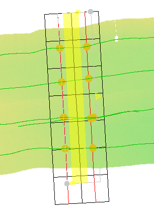
Number of outer beams to ignore | The number of data points to ignore on the outer edge of a profile that might have issues other than sound velocity. For example, when track lines overlap, the further beams can be ignored to give a better result with cleaner data. If the Preview settings... property is enabled, the outer beams that will be ignored based on this setting will be displayed in dark grey, allowing the user to determine the best value for this setting. The default value is 0 beams. |
Buffer increment (m) | To calculate the corrections needed for a profile, the application creates a subset in memory based on the location of the first and last depths of the profile in Processed Depths. This area must contain at least 95% of the depths for the profile in order to calculate the correction values. If there are not enough depths found within the area, the size of the subset is increased incrementally according to the value specified for this setting until the subset contains a sufficient number of soundings. The default value of 0.5 m |
Ignore outliers | Enable this option to ignore soundings that are not within the majority of depths of a profile when determining the corrections. If the Preview settings... property is enabled, the outlier soundings that will be ignored based on these settings will be displayed in white, allowing the user to determine the best values for this setting. To use this setting, a threshold and bin size must be specified. • Outlier threshold: This value will determine how far from the average of each bin in terms of standard deviations, to consider a sounding to be an outlier. The absolute difference of depth with the mean depth of the bin is divided by the standard deviation of depths in that bin, creating a z-score. The absolute value of the z-score must be greater than the threshold for the depth to be considered an outlier. • Outlier bins: The number of bins to split the depth profile into for determining average values along the profile for outlier determination. The default 50 bins. |
The Preview settings (2D and 3D views) option in the Correction properties can be used to view the effects of the correction values as they are selected. When this option is enabled, the data in the Subset 2D View is automatically adjusted to show the data shift for the selected correction value.
The Console window is also available as an advanced method of monitoring the corrections when running automatic corrections. This window can be opened by enabling the Tools > Options > General > Console setting. Details about the corrections will be displayed in this window as the corrections are added. The details will be colour coded to match the colours being used to display each track line in the 2D and 3D View windows, making it easy to identify which track line the correction was added to.

Each of the corrections added will be visible in the Display window as a coloured dot on the track line. A different colour is used to represent each type or state of correction, for example unsaved corrections display with a different colour than saved corrections, by default.

The colours used to represent each correction type can be defined in the properties for the Corrections layer when the Subset Editor is not open.

The type of corrections include:
• Line extents corrections: Dynamic corrections added to each end of the track line that ensure the entire line has a correction to interpolate along. These corrections are set based on the nearest slice value from a new subset.
• Subset extents corrections: Dynamic corrections that are added at the edges of the subset.
• If no corrections have been added to the track line, the extent corrections will match the value of the first correction added manually. As subsequent slice corrections are added closer to an extent, the subset extent correction for that extent will change to that of the newest slice correction added.
• If corrections have been added to the track line from previous subsets, the subset extents corrections are interpolated at the location of the subset extent along the track line between the existing corrections.
• Subset slice corrections: Depth/sound velocity value corrections that were added manually.
• Unsaved corrections: Corrections that were added but have not been saved.
• Swath Editor corrections: Any corrections that were done in Swath Editor on a line-by-line basis previous to using Subset Editor Corrections. The upgraded data will now store these sound velocity (depth of velocity) corrections in this layer with no depth correction.
• Refract.exe corrections: Any corrections that were added using the Refract.exe command line utility.
• Automatic corrections: Depth/sound velocity corrections that were added through the iterations of the automatic corrections process.
Corrections that have been added, but not saved, will be retained if another track line is selected and the user then returns to the original track line.
Adding corrections only adds them in the editor, it does not apply the corrections to the data. To apply the corrections, the Georeference Bathymetry process must be run.
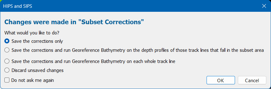
• For manual corrections, if the subset is moved, if the Stop button is clicked or if the Automatic (Subset/View) tab is selected, the following dialog box is displayed that provides options to save and run the process.
• For automatic corrections, if the Stop button is clicked or if the Manual (2D Slice) tab is selected, the following dialog box is displayed that provides options to save and run the process.
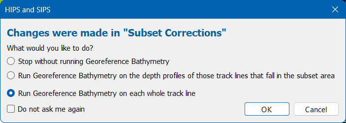
The Do not ask me again check box can be used to stop the dialog box from displaying each time and automatically use the last used option instead. The Subset Correction Save option in Tools > Options > Display > Notification can be used to change the default function, if needed.
Corrections are applied when Georeference Bathymetry is run with the correction setting enabled; it is enabled by default when run in Subset Editor. The corrections are applied by interpolating from one correction value to the next stored correction within a track line. See Georeference Bathymetry for more information on this process.
Automatic Surface Correction will apply, if it is enabled in Tools > Options > Coverages, and the surface(s) have the Keep Up to Date option enabled. To see the changes in the surface as corrections are added, applying Georeference Bathymetry to the data only in the subset is recommended.
When the process is run and the corrections are applied, an entry will be added to the Log Viewer for each method that Georeference Bathymetry was run, both Subset - Area' and 'Subset -Whole Line', for only the subset area. The entry will include the start and end profiles of the subset for which the data was processed. It will also display the options that were used when Georefence Bathymetry was run. By default, the Refraction Coefficients and Depth Corrections options are enabled when run from the Subset Editor.

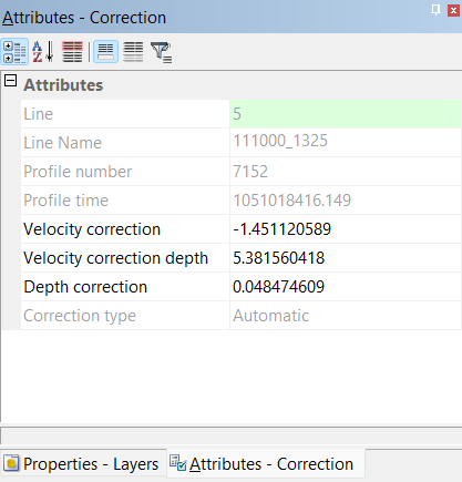
Once applied, the correction values are added to the track lines as attributes. The corrections can be selected and their details viewed in the Selection and Attributes windows. Hovering the mouse cursor over a correction in the Display window will also display a tooltip with information about the correction.
Procedure: Manual Corrections
1. Select the Corrections item in the Subset Control window.
2. Select the Manual (2D Slice) tab.
3. Enable the Preview settings (2D and 3D views) property.
4. Click Start.
5. Click the check box in the track line list for each track line to be corrected.
6. Select correction values as needed.
7. Click Save.
8. If needed, move the subset and repeat steps 3 to 5.
9. Click Stop.
10. Exit Subset Editor.
11. If needed, run the Georeference Bathymetry process.
Procedure: Automatic Corrections
1. Select the Corrections item in the Subset Control window.
2. Select the Automatic (Subset/View) tab.
3. Enable the Preview settings (2D and 3D views) property.
4. Click Start.
5. Specify the settings to use for calculating the corrections.
6. Click Run.
7. Click Stop.
8. Exit Subset Editor.
9. If needed, run the Georeference Bathymetry process.