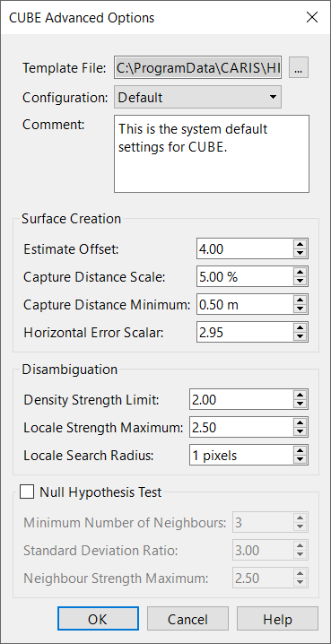
The CUBE Advanced Options window contains the more complex settings for the CUBE algorithm. These settings are saved as different “configurations” that are suitable for various types of data. The configurations are in turn stored in a template file.
When HIPS and SIPS is initially installed, it has a default template file named CUBEParams.xml in C:\ProgramData\CARIS\HIPS and SIPS\12.1\system\ that contains three configurations, Deep, Default, and Shallow. However, you can edit these configurations or create new configurations of your own design and save them in the CUBEParams.xml file. You can also create a new template file and fill it with an entirely new set of configurations.
You can use the settings in this file or select a custom configuration file. If you use a custom file, use the same syntax and structure as the CUBEparams.xml file.
If you adjust the settings in a configuration, the edited configuration must be saved to its template file before it can be applied. If you do not want to overwrite an existing configuration, select New from the Configuration file and create a new configuration.
Interface
The Advanced configuration dialog box is opened from the browse button in the CUBE Configuration field on the New Regular Gridded Surface dialog box.
Option | Description |
|---|---|
Template file | Displays the name of and path to an XML template file that contains various configurations for CUBE processing. The configurations listed in this file are shown in the Configuration menu below and also the CUBE Configuration menu in the previous window. To open a different template file: 1. Click browse, navigate to the template file, and click OK. To create a new template file: 1. Manually create a new XML file that follows the same syntax and structure as the original CUBEParams.xml file, which is normally located in 2. In this window, click the browse button, navigate to the new template file, and click OK. |
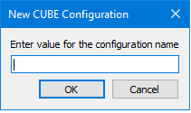
Configuration | Displays the CUBE configurations contained in the template file selected above. Selecting a configuration fills out the other fields in this window with the settings from that configuration. The default template file, • Deep: This configuration is intended to be used in areas where small features are not likely (shifting sand shoals), not important (steep grades and deep water), or separately located with side scan. This parameter set corresponds with NOAA's 2006 Complete gridding standard. • Default: This configuration contains basic, default parameters. • Shallow: This file defines the parameters for the CUBE algorithm and are intended to be used in areas of critical under-keel clearance, in areas with numerous small features, and multibeam that can stand on its own without feature-by-feature side scan correlation. This parameter set corresponds to NOAA's 2006 Object Detection gridding requirements. This menu also contains the New option, which lets you save the current settings as a new configuration in the template file. To create a new configuration: 1. If you want to save the configuration in a different template file, click the browse button by the Template File menu and load the desired template file. 2. Enter the desired settings for the configuration in the fields below. 3. In the Configuration menu, click New. 4. Enter a name for your configuration and click OK. The new configuration is now saved in the selected template file. To edit a configuration: 1. If the configuration is not in the current template file, click the browse button by the Template File menu and load the correct template file. 2. Select the configuration from the Configuration menu. 3. Adjust the settings below as desired. 4. Click OK. When the dialog asks you if you want to save the template file, click Yes. The edited configuration is now saved in the template file. |
Comment | Displays a short description for each configuration. Additional text can be added. |
Surface Creation | |
Estimate Offset | The threshold for significant offset from current estimate to warrant an the creation of a new hypothesis. The value must be between 0.1 and 10.0. |
Capture Distance Scale | Scale on predicted or estimated depth for how far out to accept data. Value is a percentage of depth used to limit the radius of influence a sounding may have on the grid. Value must be between 1.00 and 100.00. |
Capture Distance Minimum | The minimum value (in metres) on predicted or estimated depth for how far out to accept data. This value is used in conjunction with Capture Distance Scale to limit the radius or influence of a sounding. Value must be between 0.0 and 100.00. |
Horizontal Error Scalar | The value used to scale the horizontal error of each sounding when used in the radius of influence computation. Value must be between 0.0 and 10.00. |
Disambiguation | |
Density Strength Limit | The strength value used to switch from the 'density' disambiguation method to the 'locale' version when using the density & locale algorithm. Value must be between 0.00 and 5.00. |
Locale Strength Limit | Locale Strength Maximum: The maximum strength value allowed as part of the mean in the locale algorithm. Value must be between 0.00 and 5.00. |
Locale Search Radius | Locale Search Radius: The radius of the search when computing the trimmed mean. The values are in pixels and must be greater than zero. The original system default value is 1. |
Null Hypothesis test | Null Hypothesis Test: Flag used to control the application of the NULL hypothesis test. Value must be either True or False. Default value is False. |
Minimum Number of Neighbours | Minimum Number of Neighbours: During the Null Hypothesis test, this controls the minimum number of neighbours that a node must have in order to be considered for the Standard Deviating Ratio test. If the node has less the specified number, it is automatically marked as 'Null'. Values must be between 2 and 8 |
Standard Deviation Ratio | Standard Deviation Ratio: During the Null Hypothesis test, this represents the cut-off limit for the standard devotion ratio including the node in question to the standard deviation of the qualified neighbouring nodes. If the computed ratio exceeds the specified value, the node is marked as 'Null'. Values must be between 0.0 and 10.0. |
Neighbour Strength Maximum | The maximum strength value that is allowed to be considered as part of the standard deviation computations in the NULL hypothesis test. Value must be between 0.00 and 5.00. |
Procedure
1. [Optional] Click browse next to the Template File menu to select a different template file.
2. Select the desired configuration method from the Configuration drop-down list, or select New to create a new configuration method.
3. Set the settings for Surface Creation, Disambiguation, and Null Hypothesis Test as desired.
4. Click OK to save settings and return to creating a new gridded surface.