![]() CARIS HPD Paper Chart Editor
CARIS HPD Paper Chart Editor
![]() CARIS HPD Product Editor
CARIS HPD Product Editor
![]() CARIS HPD Source Editor
CARIS HPD Source Editor
![]() CARIS S-57 Composer
CARIS S-57 Composer
![]() CARIS Paper Chart Composer
CARIS Paper Chart Composer
Menu | Edit > Contours > Smooth by Direction Bias |
This command is only available if the Bathymetry Compilation module is enabled. See Modules for further information |
Smooth existing lines and areas using a safe-side direction-biased method. Smoothing reduces the number of vertices in a feature, improving the efficiency of processing these features.
The safe-side smoothing method will smooth a selection of contours and their related depth areas at the same time. If an appropriate bias is used, it is guaranteed to shift vertices to the deep side of a sloped feature, producing hydrographically safe results.
Smoothing is applied in multiple iterations, shifting points each time to minimize curvature in the lines. Points are shifted in the direction that best keeps the line to one side of its initial state. The direction is determined using contour metadata and user-specified settings.
If a contour cannot be smoothed without crossing another contour, it will not be smoothed. |
The results of the smoothing can be reversed using the Undo command.
It is recommended that this command be used on contours generated with the Bathy DataBASE catalogue as only those line features can contain a contour slope attribute. |
Interface
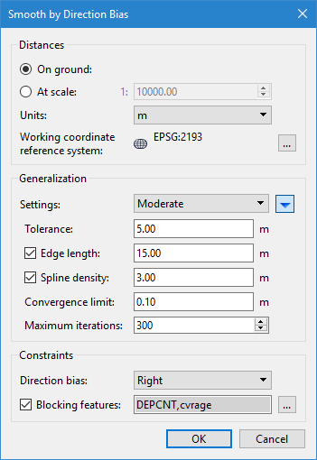
Option | Description |
|---|---|
Distances | |
On ground | The type of measurement to use for distance values. This can be distance on the ground, or distance at map scale. If using At scale, you must specify the scale to use. 1. Select a distance option. 2. If using the At scale option, use the Up and Down arrows to select a scale value or type a value directly. |
Units | The unit of measure for distance values. The default setting is controlled by the Ground Units setting under Distance in the Units category of Tools > Options. Changing this setting will automatically convert any values in other fields. If a different option is selected from the list, this selection will be remembered the next time the process is run. |
Working coordinate reference system | The coordinate reference system in which distance calculations should be done when smoothing. Using an appropriate projected coordinate reference system can reduce distortion in the resulting contours. 1. Click browse (...) . The Coordinate Reference System dialog box is displayed. See Select Coordinate Reference System for more information. 2. Select a coordinate reference system and click OK. |
Generalization | |
Settings | The level of smoothing to be applied. There are several levels available, each with a set of default values. These values can be seen by clicking the blue arrow button |
Tolerance | The minimum distance allowed between points. Points within this tolerance will be collapsed so that curves too small to see will be treated as sharp angles. Safe-side correction will compensate by moving unsafe components to half the tolerance distance from the original contour on the safe side of the line. An unscaled tolerance of 1m will be identical to a scale of 1:1000 and a tolerance of 1mm. |
Edge length | The maximum edge length of a feature. Edges longer than this will be subdivided to create multiple smaller edges. It is recommended that edges be no more than 5 times the tolerance value. 1. Enable this option. 2. Enter an edge length value. |
Spline density | The target distance between points for a smoothed spline. When this option is used, smoothing is performed in two phases, resulting in smoother contours that are still accurate. The first phase smooths based on the specified tolerance value, The second phase uses the smoothed contours from the first phase and applies additional smoothing based on this setting. Points shifted during the second phase can move to the shoal side of the first phase contours, while still guaranteeing that the resulting contour stays deeper than the original. It is recommended that this distance be less than the tolerance value. 1. Enable this option. 2. Enter a target distance value. |
Convergence limit | The minimum distance by which at least one point must be moved in a single iteration of the process in order for subsequent iterations to be run. If no points are moved at least the specified distance, the process will stop, regardless of the Maximum Iterations setting. |
Maximum iterations | The maximum number of smoothing iterations to be performed for a single run of the process. Once this number of iterations have been run, the process will stop, regardless of the Convergence Limit setting. |
Constraints | |
Slope bias | The direction bias of smoothing for contours that have a contour slope ( For hydrographic purposes, Down guarantees a hydrographically safe result and is the default value. This setting should only be changed for specific tests or if smoothing towards higher elevation is explicitly desired. This option is only displayed if some of the selected contours have a contour slope attribute value. |
Direction bias | The direction bias of smoothing for contours that do not have a defined contour slope attribute. For contours generated in CARIS applications, Right is usually the safe direction. It is, however, best to confirm that against the source dataset for which the contours were generated. Deep isolations and contours generated outside CARIS may have a reversed contour direction, which could require that Left be used to preserve safety. The Ignore option can be used to apply smoothing only to contours that have defined slope attributes. This option is only displayed if some of the selected contours do not have a defined contour slope attribute value. |
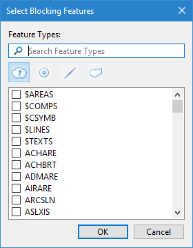
Blocking features | Blocking features are features that can block smoothing operations if the smoothing would cause contours to be pushed outside the dataset boundary. If a contour intersects a blocking feature as a result of smoothing, the smoothing will not be performed on that contour in that area. 1. Enable this option. 2. Click browse (...). The Select Blocking Features dialog box is displayer.
3. Select the feature types to use as blocking features. 4. Click OK. The selected feature acronyms are displayed in the field as a comma-separated string. |
Procedure
1. Select a feature layer with contours.
2. Select one or more contour lines.
3. Select the Smooth Contours by Direction Bias command.
4. Select the type of distance values to use.
5. Select the unit of measure for the distance values.
6. Select the Coordinate Reference System to use for distance calculations.
7. Select the level of smoothing to apply from the Settings list.
If Custom was selected for Settings, continue to the next step. Otherwise, go to the last step.
8. Click the blue arrow to view the additional fields.
9. Enter a value for the Tolerance distance.
10. [Optional] Enable the Edge length option and enter a size value.
11. [Optional] Enable the Spline density option and enter a target distance.
12. Enter a value for the Convergence Limit.
13. Select the maximum number of iterations to be run.
14. Select the Slope Bias with which to move points.
15. Select the Direction Bias with which to move points.
16. [Optional] Select Blocking features.
17. Click OK.
A progress bar is displayed to track the progress of the smoothing. Click Cancel to stop the smoothing if necessary.
The selected contours and depths areas are smoothed according to the settings defined.
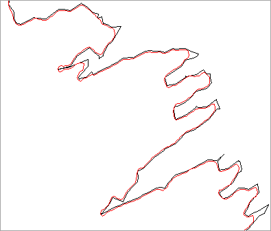
Examples
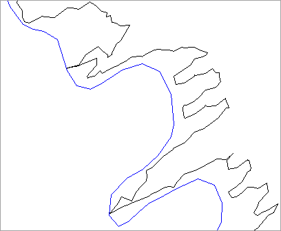
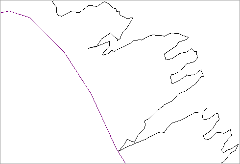
These examples show the results of applying each smoothing level to the same set of data, using the default values defined for the levels. The original contour lines are shown in black and the smoothed contours in colour.
• Minimal:
• Detailed:
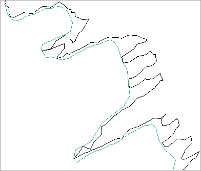
• Moderate:
• Broad:
 to expand the dialog box. A