Tool | CZMIL > Generate Grid using CUBE (Tools window) |
Generate a raster surface based on the CUBE gridding algorithm using CZMIL CPF data.
This tool is expected to be run after the One Step CZMIL processing model has been run. |
CARIS Batch process: N/A
Interface
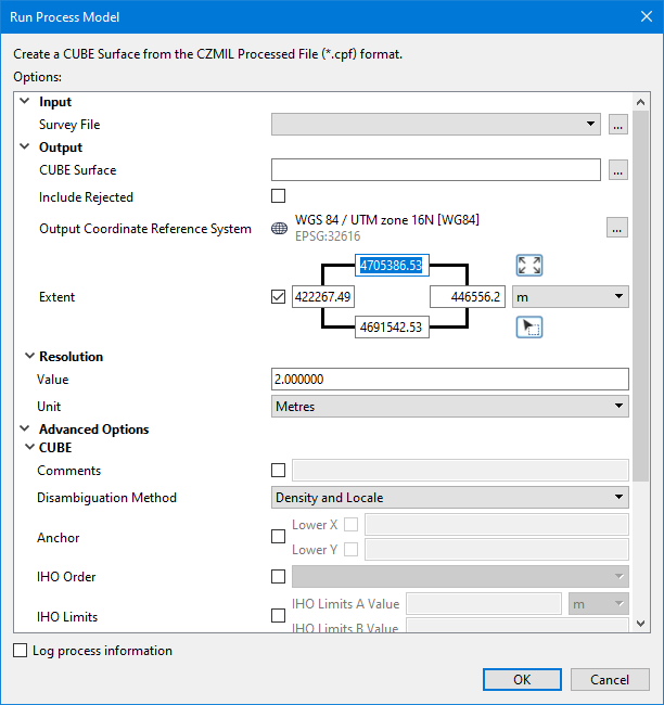
The options in this process model include:
Option | Description | |
|---|---|---|
Input | ||
Survey File | The name and location of the survey file containing the survey lines of CZMIL data. If a survey file is open in the application, a drop-down list is also provided for this option. The drop-down list allows a survey layer open in the application or the current selection (if a survey line is selected) to be used as the input survey. 1. Click the browse button (...) to launch an Open file dialog box. 2. Navigate to the relevant file. 3. Click Open. | |
Output | ||
CUBE Surface | The name and location for the output CUBE surface in CSAR format. 1. Click the browse button (...) to launch a Save file dialog box. 2. Specify a name and location for the output file. 3. Click Save. | |
Include Rejected | Include points flagged as rejected in the output surface. 1. Click the check box to enable the option. | |
Output Coordinate Reference System | The coordinate reference system (CRS) that will be used to create the output surface. 1. Click the Browse button (...) to launch the Select Coordinate Reference System dialog box. 2. Select a CRS from the list. 3. Click OK. | |
Extent | The extents that define the boundaries of the output surface. Only source data within these extents will be included in the output surface. If a survey file is open in the application at the time the process model is launched from the Tools window, the coordinates fields are populated with the extents of that survey by default. They can also be specified manually using one the three methods available: • Coordinates fields: Manually type the desired coordinates into the fields and select the unit of measure to define the extents of the surface. • Use screen extents button • Pick from screen button The Upper and Lower X and Y coordinates for the area will be updated based on the selected command. | |
Resolution | ||
Value | The ground resolution that will be used to create the CUBE surface. 1. Type a value in the field. | |
Unit | The unit of measure that will be used for the resolution value used to generate the CUBE surface. 1. Select a unit of measure from the drop-down list. | |
Advanced Options | ||
CUBE | Comments | General comments to be added to the coverage metadata. 1. Click the check box to enable the option. 2. Type the comment text in the field. |
Disambiguation Method | The disambiguation method to be used to select a hypothesis during CUBE processing. See CUBE Processing for information on disambiguation methods. 1. Select an option from the drop-down list. | |
Anchor | The coordinates of the point in the survey data that defines the output raster anchor position. 1. Click the check box to enable the option. 2. Enter the Lower X and Lower Y coordinates of the point. | |
IHO Order | The IHO S-44 Order to apply to the output raster. The order selected determines how uncertainty weighting is calculated when processing the survey data. 1. Click the check box to enable the option. 2. Select an order from the drop-down list. | |
IHO Limits | The error values to be used for IHO S-44 Order A and B if 1. Click the check box to enable the option. 2. Enter a value for each limit and select the unit of measure for IHO Limits A Value. | |
Use CHGF Mean Distance | If set, the Chebyshev approximation of the Confluent Hypergeometric Function is used to calculate the mean propagation distance of soundings to nodes. 1. Click the check box to enable the option. | |
CUBE Configuration | The CUBE configuration parameters to use to generate the raster output. The predefined options include Clicking the browse button launches the CUBE Advanced Options dialog box, which displays the detailed configuration settings for each configuration option. The predefined settings can be used or a custom configuration can be defined. See CUBE Advanced Options for more information on the CUBE configuration settings. 1. Select an option from the drop-down list. | |
Topographic Channels/ Returns | The topography data channels and data returns in the survey data from which values will be read when generating the output surface. 1. Click to populate the check box of each channel to be included. 2. Click to populate the check box of each return to be included. | |
Bathymetric Channels/Returns | The bathymetry data channels and data returns in the survey data from which values will be read when generating the output surface. 1. Click to populate the check box of each channel to be included. 2. Click to populate the check box of each return to be included. | |
Common Options | ||
Log process information | Create a log file containing the options specified when the process was run. The location of the log file is determined by the Logs setting in Tools > Options > Files and Folders. 1. Click the check box to enable this option. | |
Procedure
1. Double-click the Generate Grid using CUBE process model in the Tools window.
The Run Process Model dialog box is displayed, populated with the Generate Grid using CUBE process model.
2. Navigate to the relevant Survey File.
3. Specify a name and location for output surface.
4. Define extents for the surface, if needed.
5. [Optional] Select the Output Coordinate Reference System for the output.
6. [Optional] Specify a Resolution Value and Unit.
7. Define any Advanced Options as needed.
8. Click OK.
A progress dialog box is displayed providing progress information as the surface is generated. Similar information is also reported in the Output window.
9. When finished, click the Close button to close the dialog box and complete the process.
 : Click this button to create a surface from the current extents of the view.
 : Click this button to select a section of the displayed data. This changes the shape of the cursor. Use the cursor to drag a bounding box around the area to be included in the output.