Tool | CZMIL > Calibrate Reflectance (Tools window) |
The Calibrate Reflectance process model runs the processed CZMIL data through an algorithm to radiometrically balance all the Shallow channels and calibrate the reflectance values to be applied to the CPF files. .
CARIS Batch process: Calibrate Reflectance
Interface
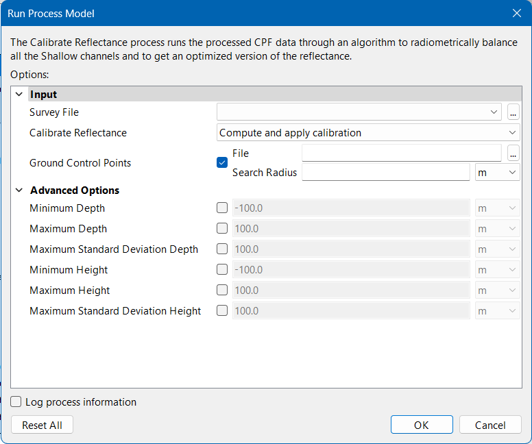
The options in this process model include:
Option | Description | |
|---|---|---|
Input | Survey File | The name and location of the survey file containing the survey lines of CZMIL data. If a survey file is open in the application, a drop-down list is also provided for this option. The drop-down list allows a survey layer open in the application or the current selection (if a survey line is selected) to be used as the input survey. Otherwise: 1. Click the browse button (...) to launch an Open file dialog box. 2. Navigate to the relevant file. 3. Click Open. |
Calibrate Reflectance | During calibration, reflectance values from the survey_reflectance_stats.csv file stored in the Lidar folder are applied to the CPF files. This option can be used to recalibrate the reflectance values prior to applying them to the CPF or to simply apply this existing values. • Compute and apply calibration: Compute the calibration parameters in the survey_reflectance_stats.csv file and then apply the new calibration values to the CPF files. • Apply calibration: Apply the existing calibration values from the survey_reflectance_stats.csv file to the CPF files. 1. Select an option from the drop-down list. | |
Ground Control Points | A CSV File containing ground control points, which are reflectance measurements of targets like road, grass, bare earth, tarmac, etc. normally collected using a hand-held spectrometer at Green wavelength and the corresponding geographical locations. The measurements are used to calibrate the reflectance values. The ground control points file contains 4 columns of reflectance measurements and their geographical positions in the format “ID, Latitude, Longitude, Reflectance”. A Search Radius must also be specified. This is the maximum horizontal distance from a control point that will be considered for calibration. 1. Click the check box to enable the option. 2. Click the File browse button (...) to launch an Open file dialog box. 3. Navigate to the relevant file and click Open. 4. Specify a value and unit of measure for the Search Radius. | |
Advanced Options | Minimum Depth | The minimum depth considered for bathymetric calibration. This is used to ignore the breakwater zone, which would be survey specific. If not set, a default of -100.0 metres is used. 1. Click the check box to enable the option. 2. Specify a value and select a unit of measure. |
Maximum Depth | The maximum depth considered for bathymetric calibration. This is used to ignore the extinction depth zone, which would be survey specific. If not set, a default of 100.0 metres is used. 1. Click the check box to enable the option. 2. Specify a value and select a unit of measure. | |
Maximum Standard Deviation Depth | The maximum standard deviation of channel returns for a bathymetric shot to be considered for calibration. System vertical accuracy (bathymetric) is recommended. If not set, a default of 100.0 metres is used. 1. Click the check box to enable the option. 2. Specify a value and select a unit of measure. | |
Minimum Height | The minimum height from bare earth considered for topographic calibration. If not set, a default of -100.0 metres is used. 1. Click the check box to enable the option. 2. Specify a value and select a unit of measure. | |
Maximum Height | The maximum height from bare earth considered for topographic calibration. This is used to ignore trees and buildings, which would be survey specific. If not set, a default of 100.0 metres is used. 1. Click the check box to enable the option. 2. Specify a value and select a unit of measure. | |
Maximum Standard Deviation Height | The maximum standard deviation of channel returns for a topographic shot to be considered for calibration. System vertical accuracy (topographic) recommended. If not set, a default of 100.0 metres is used. 1. Click the check box to enable the option. 2. Specify a value and select a unit of measure. | |
Log process information | Create a log file containing the options specified when the process was run. The location of the log file is determined by the Logs setting in Tools > Options > Files and Folders. 1. Click the check box to enable this option. | |
Procedure
1. Double-click the Calibrate Reflectance process model in the Tools window.
The Run Process Model dialog box is displayed, populated with the Calibrate Reflectance process model.
2. Click the Survey File browse button (...) and navigate to the relevant file.
3. Select an option from the Calibrate Reflectance drop-down list.
4. [Optional] Enable the Ground Control Points option then select the relevant File and specify the Search Radius.
5. Define any other necessary options.
6. Click OK.
A progress dialog box is displayed providing information about the data being optimized. Additional information is also provided via messages in the Output window.