Menu | Tools > Features > Critical Sounding Detection |
CARIS Batch | Detect HIPS Critical Soundings |
Designate critical soundings from a surface using the Critical Soundings Detection tool to automatically find and designate shoal or deep soundings in a surface attribute layer.
The detection process first contours the selected surface. By default, a step interval equal to half the resolution of the surface is used. Contouring can also be done with a user-defined value, or with specific levels.
Then any isolations (closed contours which have no contours inside them) are identified. The direction within these isolations is known (i.e. either shoaling or deepening). Based on the direction within the isolation, a shoal or deep is flagged on the HIPS data. You can define these flags, and possible attribute values as well, in the Critical Soundings Detection dialog box.
As well, radius filtering can be employed to help identify the critical sounding within clusters of soundings around detected features.
Also, a Maximum Isolations for Detection option enables the detection process to stop if a set maximum number is exceeded.
See also Critical Soundings
Interface
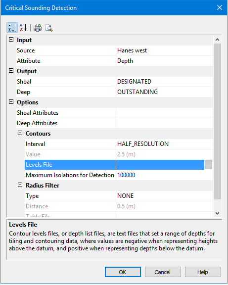
These options are set in the Critical Sounding Detection dialog box. A short description of each field is displayed in the Description Panel at the bottom of the dialog box.
Option | Description |
|---|---|
Input | |
Source | Select a surface by name from the list of surfaces currently open in HIPS. |
Attribute | Select a surface attribute layer, such as Depth, from the drop-down list. |
Output | At least one Output type must be set. |
Shoal | Click in the field to select Designated, Outstanding or Examined from the drop-down list. |
Deep | Click in the field to select Designated, Outstanding or Examined from the drop-down list |
Options | |
Shoal Attributes | Click in the field to open the Shoal Attribute Configuration dialog box and set attributes associated with the detected soundings. See Setting Attributes for Shoal and Deep Soundings |
Contours | See Contour settings. |
Interval | Set the distance between contours using either: • Half Source Resolution: the interval is a value equal to half the resolution of the selected surface (default setting). • User-defined Value: a fixed value set in the Value field. • Levels File: Browse to the location of the contour levels file, and select the file to apply. |
Value | A suer-defined contour interval. This value will be displayed using the default Horizontal Length units as set in Tools > Options > Display > Units |
Levels File | • Browse to the location of the contour levels file, and select the file to apply. |
Maximum Isolations for Detection | Enables the detection process to stop if a set number of detected isolations is exceeded. • Isolations are closed contours which have no contours inside them. 1. Set a value for the maximum isolations or accept the default value of 100,000 |
Radius Filter | See Radius Filters. |
Type | Select from the drop-down list: • None - no filtering is applied • Distance - applies the radius filter value set in the Distance field below. • Table File - applies a file containing a table of values |
Distance | If you set Distance as the type of filter, the Distance field is activated. 1. Type the length of the radius • This value is displayed in the default Horizontal Length units as set in Tools > Options > Display > Units. |
Table File | If you select Table File as the type of filter, the field is activated. See Browse to the location of the Table levels file, and select the file to apply. |