Menu | Tools >HIPS and SIPS >Beam Pattern >Create > SIPS Backscatter |
Tool |
|
CARIS Batch | Create SIPS Beam Pattern |
Menu | Tools >HIPS and SIPS >Beam Pattern >Create > SIPS Backscatter |
Tool |
|
CARIS Batch | Create SIPS Beam Pattern |
Beam pattern files can be created from SIPS backscatter data from a line or lines selected in the Display window.
Interface
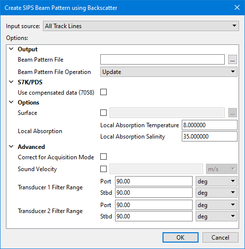
Beam pattern creation using SIPS Backscatter uses the following dialog box:
Option | Description |
|---|---|
Input Source | The input source for the beam pattern file. The options available include: • Selected Track Lines: This setting will create the file using only track lines that are currently selected. This setting is selected by default if lines were selected before opening the dialog box. • <HIPS track lines layer>: This setting will create the file using all track lines in the selected layer. All layers containing track lines shown in the Layers window are included in the list as available sources, including filter layers. • All Track Lines: This setting will create the file using all track lines from all datasets currently open in the application. This setting is selected by default if no lines were selected when the dialog box was opened. |
Output | |
Beam Pattern File | Name and destination for the beam pattern file. 1. Click the browse button (...) in the Beam Pattern File field and enter a name for the file. 2. Click Save. |
Beam Pattern File Operation | If a beam pattern file already exists for the selected data, this field displays Update, and the existing beam pattern will be applied. 1. [Optional]] Select Overwrite to replace the existing file with a new beam pattern. |
S7K | |
Use compensated data (7058) | 1. Select this option to use compensated intensity data instead of raw data. If no compensated data is found on a line, the line will not be used for the beam pattern. |
Options | |
Surface | The path to the surface used to compute the local bottom slope used in the calculations of real incidence angle and ensonified area. The default elevation band will be used. If surface is not set, the processed bathymetry will be used by default. 1. Select the check box to enable the browse (...) button. 2. Browse to and select a surface. |
Local Absorption | Correction for transmission loss using temperature and salinity values. 1. Set the temperature value in degrees. The default value is 8.00 2. Set the salinity value as parts per thousand. The default value is 35 parts per thousand. |
Advanced | |
Correct for Acquisition Mode | Enable this option to have each acquisition mode separated into a different beam pattern based on waveform and pulse length. |
Sound Velocity | The sound velocity values applied during slant range correction. This option will override the use of Surface Sound Speed (SSP) data. When SSP is not available a value of 1500 m/s is used. 1. Click the check box to enable the option. 2. Enter a value and select the units from the drop-down list. |
Transducer1 (Angle Filter) | This field displays the angle from nadir values set for Transducer1 in Port and Starboard fields. 1. Set values in degrees of the angle to port from nadir. 2. Set values in degrees of the angle to starboard from nadir. |
Transducer2 (Angle Filter) | This field displays the angle from nadir set for Transducer2 (in a dual system) in Port and Starboard fields. 1. Set values in degrees of the angle to port from nadir. 2. Set values in degrees of the angle to starboard from nadir. |
Procedure
1. Open the track line data.
2. [Optional] Select the relevant track lines.
3. Select the Create SIPS Beam Pattern using Backscatter command.
The Create SIPS Beam Pattern using Backscatter dialog box is displayed.
4. Select the Input source.
5. Set the name and designation for the Beam Pattern File.
6. Define any other necessary options.
7. Click OK to create the beam pattern file.
The new file will be created with a *.bbp extension.
You can view a loaded beam pattern in the Beam Pattern View window or the Signal Display window, where it will appear as a yellow line. See View Beam Pattern and Open Signal Display Window.
Menu | Tools >HIPS and SIPS >Beam Pattern >Close |
Tool |
|
The current beam pattern must be closed before another beam pattern can be created.
8. Click the Close Beam Pattern command.

