Menu | Tools > Coverages > Grid > CUBE Raster Surface |
Generate a raster surface from the points in an existing coverage using a CUBE gridding algorithm.
This is useful if you wish to generate a raster surface containing uncertainty bands generated through the Add Computed Band command.
Related commands:
• New Variable Resolution Surface
Interface
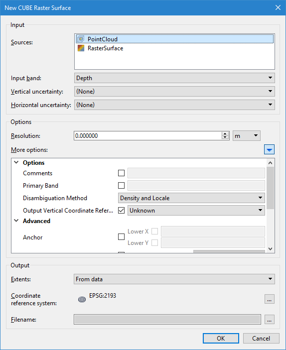
The New CUBE Raster Surface dialog box is used to define the parameters for generating a CUBE surface.
Option | Description |
|---|---|
Input | |
Sources | The input data for the process. Any point cloud and/or raster surface currently open in the application can be selected. If more than one source is selected, points from all selected coverages will be used. If a coverage was selected before launching the dialog box, that coverage is selected by default. 1. Select each data source to include in the CUBE surface. • To select a range of sources, press and hold the <Shift> key then click the first and last source in the range. • To select multiple individual sources, press and hold the <Ctrl> key then click each of the relevant sources. |
Input band | The name of the band in the source coverage containing the elevation values to be used to compute the CUBE surface. |
Vertical uncertainty | The name of the band in the source coverage containing vertical uncertainty values. If (None) is selected, the IHO Order option must be populated. |
Horizontal uncertainty | The name of the band in the source coverage containing horizontal uncertainty values. If (None) is selected, horizontal uncertainty values will be treated as zero. |
Options | |
Resolution | The resolution of the output surface. 1. Use the Up and Down Arrow buttons to select a value or type a value in the field. 2. Select the unit of measure for the resolution value. |
More options | Click the blue arrow button to expand a list of additional options. |
Comments | General comments to include in the metadata of the output surface. 1. Click the check box to enable the option. 2. Type the desired text in the field. |
Primary Band | The name to assign to the primary band in the output surface. 1. Click the check box to enable the option. 2. Type the desired text in the field. |
Disambiguation Method | The method to use for selecting a hypothesis for disambiguation. 1. Select an option from the drop-down list. |
Output Vertical Coordinate Reference System | The vertical coordinate reference system (CRS) to assign to the output surface. 1. Click the check box to enable the option. 2. Select an option from the drop-down list. |
Anchor | The coordinates of the point to use as the anchor position for the output surface. 1. Click the check boxes to enable each of the options. 2. Type the coordinates in the fields. |
IHO Order | The IHO S-44 order to apply to the output surface. 1. Click the check box to enable the option. 2. Select an option from the drop-down list. |
IHO Limits | The IHO S-44 Order 'A' and 'B' error values to be used if IHO Order is set to • IHO Limits A Value: The minimum error value for the depth-dependent error • IHO Limits B Value: The percentage of each depth value used to calculate horizontal error. 1. Click the check box to enable the option. 2. Use the Up and Down Arrow buttons to select a value for IHO Limits A Value, or type value in the field. 3. Select the unit of measure for A Value. 4. Enter a value for IHO Limits B Value. |
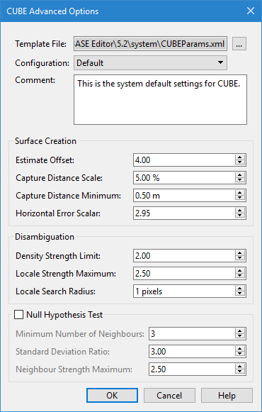
CUBE Configuration | The CUBE configuration parameters to use for generating the CUBE surface. Three options are available in the drop-down list, each one provides a different set of default values for the configuration settings. 1. Click the check box to enable the option. 2. Select an option from the drop-down list. 3. Click the browse button (...) to launch the CUBE Advanced Options dialog box. See Advanced Options for CUBE Configuration for information on this dialog box.
4. Define any necessary settings and click OK. |
Use CHGF Mean Distance | Enable this option to use the Chebyshev approximation of the Confluent Hypergeometric Function for mean propagation distance of soundings to nodes. |
Output | |
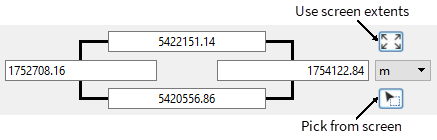
Extents | The extent of the resulting surface. Only source data within these extents will be included in the output surface. The From data option is selected by default. This option computes an extent that covers all selected input coverages. The Custom option provides three different methods for defining the extent of the data to be included. When this option is selected, the dialog box will change to provide the following controls: • Coordinates fields: Manually type the desired coordinates into the fields and select the unit of measure to define the extents of the surface. • Use screen extents button: Click this button to create a surface from the current extents of the view. • Pick from screen button: Click this button to define a section of the displayed data. This changes the shape of the cursor. Use the cursor to drag a box around an area. The Upper and Lower X and Y coordinates for the area will be updated based on the selected command. |
Coordinate Reference System | The CRS of the resulting surface. 1. Click the browse button (...) to open the Select Coordinate Reference System dialog box and set the output system. See Coordinate Reference System Selection for information on this tool. |
Filename | The name and location of the output surface file. |
Procedure
1. Select the source coverage in the Layers window.
2. Select the New CUBE Raster Surface command.
The New CUBE Raster Surface dialog box is displayed.
3. Select the coverage(s) to be used as source data.
4. Select the band in the source coverage containing the elevation values.
5. Select the source bands for Vertical and Horizontal uncertainty.
6. Specify a value and unit for the Resolution of the output surface.
7. Define any other necessary Options.
8. Select the Extents for the output surface.
9. Select the CRS to use for generating the output surface.
10. Define the name and output location for the surface.
11. Click OK.
The CUBE surface is generated in the specified location and opened in the application.