Menu | Select > Features By > Geometry Comparison |
Tool |
|
Menu | Select > Features By > Geometry Comparison |
Tool |
|
The Select by Geometry Comparison command is used to select features on a target layer using the geometries from a specified source. The source can be the currently active selection or it can be the geometries in another layer open in the application. If using another layer as the source, all features on that layer will be referenced. To limit the geometries used, a filter layer can be created from the original source data and that filter layer can then selected as the geometry source.
Filters are not recognized for all file formats. If the data source has a filter, but the filter is not recognized, it will be ignored during processing and statistics will be generated using all data in the data source instead of what is being displayed for the layer. |
Operators are provided to define the criteria necessary for a target feature to be included in the selection. This criteria identifies the relationship required between the source geometries and the target features, for example, whether the target features are completely contained within the source geometries or if the target features simply touch the source geometries.
When selecting operators, it is important to understand that the geometry of a feature consists of a boundary, an interior, an exterior and geometric dimensions (1-dimensional, 2‑dimensional, etc). These components differ for each of the main feature types and are used by the operators to determine which features meet the selection createria. The table below explains the geometry component for each feature type.
Feature Type | Description |
|---|---|
Point Multi-point | • Boundary: none, point features have no boundary • Interior: the point itself • Exterior: the space outside the point • Dimensions: 0, points have neither a length, width nor height |
Line Multi-line | • Boundary: the two end points of the line • Interior: the points between the two end points of the line • Exterior: the space outside the line • Dimensions: 1, length |
Area Multi-area | • Boundary: the inner and outer polygon boundaries of the area • Interior: the space within the polygon’s boundaries • Exterior: the space outside the polygon's boundaries (including the area inside any inner rings) • Dimensions: 2, width and height |
If an area feature contains holes, the area has both an inner boundary and an outer boundary, with the inner ring being the inner boundary. |
Related commands:
• Select by Superselected Buffer
• Select Features Inside Selected Areas
• Select Features Intersecting Selected Areas
• Remove Others from Selection
Interface
The Select by Geometry Comparison command uses the following dialog box.
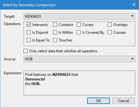
Option | Description | |
|---|---|---|
Target | The layer from which features will be selected. The drop-down list is populated with all layers currently open in the application that contain geometry features. | |
Operators | The required relationship between the source geometries and the target features. Selecting multiple operators will result in the selection of features that meet any or all of the selected operators, depending on whether the Only select data that satisfies all operators option is enabled. Each of the operators is explained below. The explanations include an example where A (black) is the source geometry and B (red) is the target feature. It is possible that a feature can meet the requirements for multiple operators. For example, if a feature returns TRUE for Is Within, it will also return TRUE for Is Covered By. | |
Intersects |
| The boundaries and/or interiors of the target features and the source geometry intersect in any way. This is the oppposite of Is Disjoint. |
Is Disjoint |
| Neither the boundaries nor the interiors of the source geometry intersect with the target features. This is useful for identifying features that are outside of the data extents. This is the oppposite of Intersects. |
Crosses |
| The target feature and source geometry cross if their interiors intersect, and the geometry of that intersection has a dimension that is less than either the source or the target. |
Overlaps |
| The target feature and source geometry overlap if they have the same dimension and their interiors intersect, but the geometry of the intersection is not equal to either the source or the target. |
Contains |
| The target feature contains the source geometry. Every point of the source geometry is contained in the boundary of the target feature, and at least one point of the source geometry must be on the interior of the target feature. This is the oppposite of Is Within. |
Is Within |
| The target feature is within the source geometry. Every point of the target feature is within the boundary of the source geometry, and at least one point of the target feature must be on the interior of the source geometry. This is the oppposite of Contains. |
Covers |
| The target feature completely covers the source geometry. All points of the source geometry are on the boundary or on the interior of the target feature. This is the oppposite of Is Covered By. |
Is Covered By |
| The target feature is completely covered by the source geometry. All points of the target feature are on the boundary or on the interior of the source geometry. This is the oppposite of Covers. |
Touches |
| The boundaries of the source geometry and the target feature intersect but the interiors do not intersect. |
Is Equal To |
| The source geometry and the target feature have the same boundary and interior. |
Only select data that satisfies all operators | This option can be enabled when more than one operator is selected and it is necessary for target features to meet all specified criteria in order to be selected. | |
Source | The geometry source. The drop-down list is populated with all layers currently open in the application that contain geometry features. If a selection was active when the dialog box was opened, “Selection” will also be available in the list; this option will use the geometries of the active selection as the source. | |
Expression | The expression that will be run to perform the selection. The expression is built from the values selected for each of the options in the dialog box. Each time an option is changed, the expression will be automatically updated. | |
Procedure
1. [Optional] Select the relevant feature objects in the 2D View if using the active selection as the geometry source.
2. Select the Select by Geometry Comparison command.
The Select by Geometry Comparison dialog box is displayed.
3. Select a Target from the drop-down list.
4. Click the check boxes of the relevant Operators.
5. Select a Source from the drop-down list.
The Expression field is populated with the selection expression as defined by the values selected.
6. Click OK.
All features from the specified target that meet the selection criteria are added to the Selection window.


