A coordinate reference system is any system that references a point location on the earth’s surface with respect to a pre-determined set of intersecting east-west and north-south lines. For instance, parallels and meridians are used throughout the world as the geographic (latitude/longitude) coordinate system or geographic grid. Any point location, or area, on earth, can be accurately referenced by means of its geographic coordinates.
Although the system of latitudes and longitudes based on the prime meridian of Greenwich is widely used, not all countries adhere to this convention. Some European countries such as Germany and France use a prime meridian of their own choosing for at least some of their maps.
Spherical and plane coordinates
Geographic coordinates are considered spherical coordinates because they represent circles (or ellipses) that reference points on a spherical (spheroidal) surface. Meridians are not equi-distantly spaced lines over the entire globe nor can they form the basis of a square net on any of the useful map projections. To overcome the limitations of a spherical coordinate system, plane coordinates have been invented. Plane coordinates provide a system of two sets of straight lines that on a flat map-sheet intersect each other at right angles. A plane coordinate system consists of true squares on the map that are superimposed on the geographic grid.
The Universal Transverse Mercator grid system (UTM) has its origins in the military grid coordinate system but is now also widely used superimposed on Transverse Mercator and Lambert Conformal maps developed for civilian use in Canada and the United States, as well as many other countries. The UTM grid system consists of 60 grid zones each 6 degrees longitude in width. An additional half-degree on each side provides for overlap into the adjacent zone. The origin of each grid zone lies at the intersection of its central meridian (which is a straight north-south line occupying the central position of the grid zone), and the equator (which is a straight east-west line).
To have all grid line values (called Eastings and Northings) increase to the right and up respectively, the central meridian for each grid zone in the northern hemisphere has been given an arbitrary value of 500 000 metres east, and the equator an arbitrary value of 0 metres north increasing in values towards its bounding northern latitude. In the southern hemisphere the equator has been given the arbitrary value of 10 000 000 metres north decreasing towards its bounding south latitude.
The UTM grid uses the metre as its basic unit of length and the grid is a network of squares, each 1000 metres wide. Numbers on the grid line increase towards the right (Eastings) and up (Northings). The procedure is to first state the Eastings value then the Northings value.
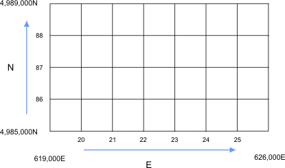
UTM Eastings and Northings of part of the 1:50,000 NTS map “St Stephen” New Brunswick, (Canada) and Maine, (United States of America)
Elevation differences can be represented by a vertical coordinate system. A vertical coordinate system has only one axis. One point on the axis is designated as the origin or vertical datum and is assigned a coordinate value of 0. Other points have a vertical coordinate equal to their elevation difference from the origin. Mean sea level is commonly used as a vertical datum.
In giving the coordinates of a point on a map, or the “windowed out” corner coordinates of part of a map, the first step is to determine the 1000 metre grid square within which the point lies. The grid coordinates of its lower left-hand corner designate each grid-square. For a particular point location within the grid square the coordinates may be read to a tenth of the grid, which is one hundred metres. Another digit may be read to locate a point within ten metres accuracy.
Choosing the coordinate system
CARIS software uses four horizontal coordinate systems:
Coordinate System
Description
NEMR
The coordinates are expressed as Northings and Eastings of a projection in metres on the ground (hence Northings and Eastings in MetRes).
Distances and bearings can be carried across adjacent map sheets with this coordinate system, meaning that a continuous database can be established.
Its application includes the atlas grid and is used primarily in land-based applications.
NRMR
Coordinates expressed in metres on the map have no reference to a specific location on the ground (hence Non Registered, MetRes).
This type of coordinate system is used when a map needs to be created for demonstration purposes only where the information necessary for relating the map to the real world (control points) is not necessary.
LLDG
Coordinates are expressed in latitude and longitude in decimal degrees on a reference ellipsoid (hence Latitude and Longitude in Decimal deGrees).
Data may be digitized in Latitude and Longitude by typing the coordinates or by batching a number of measurements and applying them at one time. Another method of obtaining data is to digitize in another coordinate system and then convert to LLDG.
CHMR
Coordinates are expressed in metres at the chart scale (hence CHart in MetRes).
All distances and bearings are relative to that chart. Thus a stored position near the top right-hand corner of the physical map would be similar to the actual map dimensions. This stored position can nevertheless be transformed to Northings and Eastings or geographic latitude and longitude as required. This coordinate system is used primarily for hydrographic charting.