Menu | Tools > Coverages > Modify > Generalize |
Pop-up | Generalize |
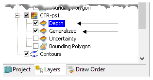
Create a product surface by generalizing a finalized surface. When the generalized surface is created, it is listed in the Layers window and shown in the Display window.
Also created is a Generalized layer which displays the nodes that were affected during the product surface-creation process.
• Nodes that have been modified are given a status flag of 1.
• Nodes that retain their original values are given a status flag of 0.
The status of the nodes is displayed in the tool tip, as illustrated below, which shows Generalized = 1.
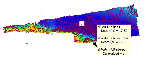
In the example above, the filter in the Properties for the Generalization layer has been set to show only the nodes which have been modified by the product surface. These are displayed as red dots in the example above.
The generalize process is described in Generalizing a Surface.
Related commands:
• Finalize
Interface
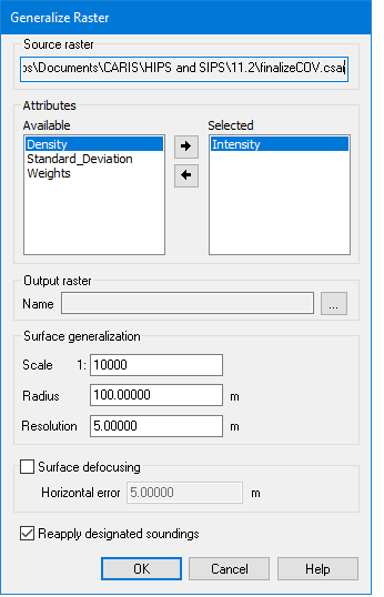
The generalize options are contained in the Generalize Raster dialog box.
Procedure
1. Open the finalized surface.
2. Select the Surface layer in the Layers window.
3. Select the Generalize command.
The path and file name of the selected surface is displayed at the top of the dialog box.
4. [Optional] Select one or more attribute layers to add to the Depth layer in your product surface.
5. In the Output Surface field, browse to save a name and location for the new product surface.
6. Type a scale ratio that best suits the type of surface.
The scale of the Surface should match the scale of the product being created. For example, if you are creating a product surface that is going to be used for an ENC approach to a harbour, then use the appropriate scale for an approach.
The scale determines the radius used for generalizing the contours of the Surface. The Radius value changes as the Scale value is changed.
The Resolution value sets the node spacing of the generated surface.
7. Type Scale, Radius and Resolution values, as needed.
8. [Optional] Select Surface Defocusing to implement this option.
The defocusing operation requires you to apply a horizontal error value. This value must be derived from the errors values associated with the data.
9. Type a Horizontal Error value.
10. Select the Reapply Designated Soundings check box to make sure that designated soundings are applied to the surface.
11. Click OK.