Menu | Tools > HIPS and SIPS > Data Filters > Processed Depths |
CARIS Batch |
This command is used to filter data using an input surface and either:
• a scaled standard deviation or uncertainty threshold
• a static threshold value
• a polygon boundary
• a noise confidence threshold
Any soundings that fall outside the filter threshold will be flagged as rejected.
Interface
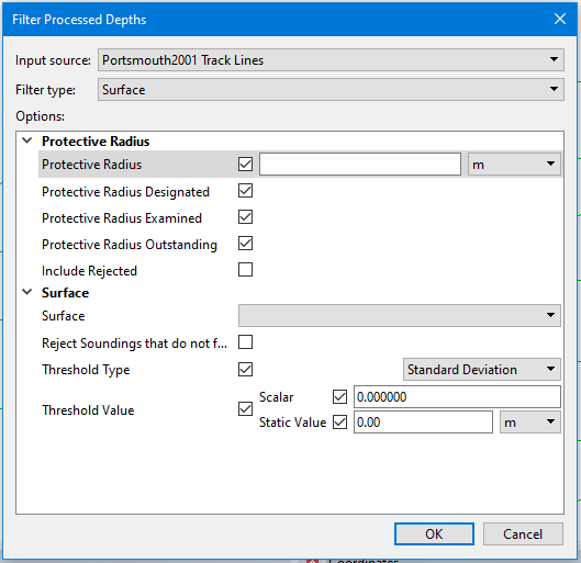
Filter settings are defined in the Filter Processed Depths dialog box.
Option | Description |
|---|---|
Input source | The input data to be filtered. The drop-down list is populated with all HIPS data currently open in the application. |
Filter type | The type of filter to apply to the data. • Select Surface to filter the data using the area of a surface. • Select Polygon to filter the data using an area within a bounding polygon. • Select Noise Confidence to filter the data based on noise confidence values. |
Protective Radius Options | |
Protective Radius | Enable this option to apply a protective radius around critical soundings. When this option is enabled, neighbouring soundings inside the protected area will not be filtered. 1. Click the check box to enable the option. 2. Type a radius value in the field and select a unit of measure. |
Protective Radius Designated | Enable this option to apply the protective radius to soundings flagged as Designated. |
Protective Radius Examined | Enable this option to apply the protective radius to soundings flagged as Examined. |
Protective Radius Outstanding | Enable this option to apply the protective radius to soundings flagged as Outstanding. |
Include Rejected | Enable this option to include data that was previously flagged as rejected. |
Surface Filter Options | |
Surface | The name and location of the surface from which data will be used to calculate the filter threshold if using the Surface filter type. The primary elevation band of the surface will be used by default. The drop-down list is populated with all surfaces currently open in the application. 1. Click the check box to enable the option. 2. Select a surface from the drop-down list. |
Reject soundings that do not fall on the surface | Enable this option to reject soundings that did not contribute to the grid node depth when the surface was originally created. This is determined by computing the radius of influence for each sounding using the grid type calculation that was used to create the surface (e.g. Swath, CUBE etc). If the sounding is not located within that radius, it is flagged as Rejected. Soundings are only rejected by this option in a very specific set of circumstances. Enabling this option often has little visible effect. |
Threshold Type | The type of threshold to use for the filter based on the data available in the filtering surface. • If the surface has a Standard Deviation or Uncertainty band, a scale can be used to filter points according to their Standard Deviation or Uncertainty values. Points that are not within the range of the specified scale will be flagged as rejected. • If the surface has both Standard Deviation and Uncertainty bands, the application can first determine which is the Lesser or Greater value between standard deviation and uncertainty, depending on the selected threshold type. A scalar value can then be used to filter the winning points based on their standard deviation or uncertainty values. Points that are not within the range of the specified scale will be flagged as rejected. • A static value threshold is used if the other bands are not present in the surface. With this threshold, a specific value is used for the filter. |
Threshold Value | The value to reject all soundings that fall outside the specified threshold. • Scalar: This option is used when filtering using a scaled standard deviation or uncertainty filter. • Click the check box to enable the option. • Type a value in the field. • Static Value: This option is used when filtering for a specific value or values greater/less than a specific value. • Click the check box to enable the option. • Type a value in the field. • Select a unit of measure for the filter value. 1. Click the check box to enable the Threshold Value fields. 2. Click the check box of the relevant threshold value type. 3. Enter the threshold value as needed. |
Polygon Filter Options | |
Accept Data | Enable this option to flag filtered data as Accepted instead of the default Rejected. |
Geometry | The feature layer containing the 1. Click the check box to enable the option. 2. Select a feature layer from the drop-down list. |
Extract Type | Specify whether the filter should reject data found inside or outside of the polygon geometry. • Inclusive: filter all data inside the polygon, including data that touches the polygon. • Exclusive: filter all data outside the polygon. 1. Click the check box to enable the option. 2. Select an option from the drop-down list. |
Noise Confidence Filter Options | |
Threshold | Select the noise confidence threshold by which to filter the data. Points with a noise confidence value greater than the threshold will be flagged as rejected. A higher threshold value will allow points with a higher noise confidence to be included in the filtered data. A low threshold value will retain only the points with a low noise confidence value, resulting in less noise in the filtered data. 1. Click the check box to enable the option. 2. Use the slider bar to select the confidence Threshold. |
Procedure: Filter using a surface
1. Open or create a surface.
2. Select the Processed Depths command.
The Filter Processed Depths dialog box is displayed.
3. Select the track lines to be filtered from the Input Source list.
4. Select Surface from the Filter Type list.
This displays the Surface filter options.
5. Set any Protective Radius options as needed.
6. Select the surface to filter by, and set the threshold options, as described above.
7. Click OK.
Procedure: Filter using a polygon:
1. Create a feature layer and digitize a cvrage object, or open an existing hob file that contains coverage (cvrage) objects
2. Select the Processed Depths command.
The Filter Processed Depths dialog box is displayed.
3. Select the track lines to be filtered from the Input Source list.
4. Select Polygon from the Filter Type list.
This displays the Polygon filter options.
5. Set any Protective Radius options as needed.
6. Select the hob/feature layer that contains the cvrage objects to filter by.
7. Select the relevant Extract Type option.
8. Click OK.
Procedure: Filter using noise confidence values
1. Select the Processed Depths command.
The Filter Processed Depths dialog box is displayed.
2. Select the track lines to be filtered from the Input Source list.
3. Select Noise Confidence from the Filter Type list.
This displays the Confidence Threshold filter option.
4. Set any Protective Radius options as needed.
5. Set the Threshold value.
6. Click OK.