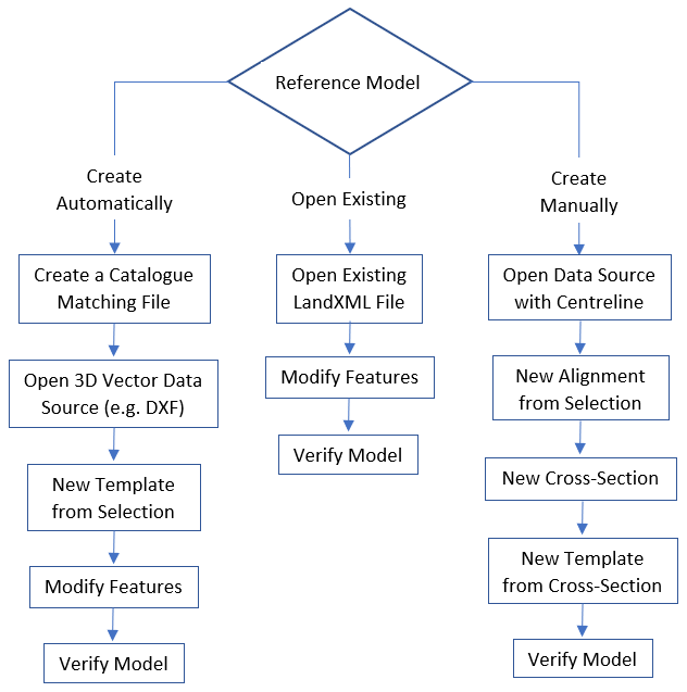
There are several workflows available to begin working with a reference model. The image below shows the recommended workflows, with descriptions for each step in the table that follows.
Method | Step | Description |
|---|---|---|
Create Automatically | This method involves importing 3D vector data as a reference model using a catalogue matching file to map the features and their attributes. | |
Create a catalogue matching file | A matching file is used to map acronyms for feature objects and attributes when importing the source data into a reference model. See Create a Catalogue Matching File. | |
Open 3D Vector Data Source (e.g.DXF) | 3D vector data is feature data that contains elevation attribute values. This data can be opened directly in the application and used to generate a reference model. See Open File. | |
New Template from Selection | Automatically create the features of a reference model using the geometry and attributes of existing polygon features. See New Template from Selection. | |
Modify Features | Alterations may be needed in the automatically‑generated features. This can be done using any of the following commands: | |
Verify Model | Verify that the requirements for all features and attributes in the selected reference model have been met. See Verify Model. | |
Open Existing | This method opens an existing reference model in LandXML format. | |
Open Existing LandXML fie | Reference model files in LandXML format can be opened directly in the application. See Open a Reference Model. | |
Modify Features | Updates may be needed in the existing reference model features. This can be done using any of the following commands: | |
Verify Model | Verify that the requirements for all features and attributes in the selected reference model have been met. See Verify Model. | |
Create Manually | This method uses a vector data line feature as a reference to manually create reference model features that will then be used to generate the remainder of the reference model. | |
Open Data Source with Centreline | A vector data source containing a centreline feature can be used as a starting reference for creating a reference model. Vector data can be opened directly in the application. See Open File. | |
New Alignment from Selection | With a centreline data source open, that line can be used to create an alignment feature for the new reference model. See New Alignment From Superselection/ Selection. | |
New Cross-Section | A cross-section suitable to be applied along the centreline can then be created. See New Cross-section. | |
New Template from Cross-Section | The alignment and the cross-section created in the previous steps can then be used to create a new template, which will generate the remaining features for the reference model and populate their properties. See New Template from a Cross-Section. | |
Verify Model | Verify that the requirements for all features and attributes in the selected reference model have been met. See Verify Model. | |
Additionally, the New Model command can be used to create a new empty model. With this method, all features in the model must be created manually and all attributes defined. See New Model for more information on this command.