Menu | Tools > Limits and Boundaries > Median Line |
Tool |
|
Menu | Tools > Limits and Boundaries > Median Line |
Tool |
|
A median line is a mathematical solution for a boundary at equal distance from two adjacent or opposite States. This line is called an equidistant line when the coastlines are adjacent and a median line when they are opposite. The same command is used for both cases.
Median lines are created from baselines on two separate layers, one for each State or group of States.
Interface
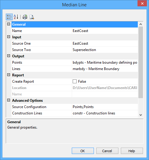
The Median Line command uses the following dialog box.
Group | Option | Description |
|---|---|---|
General | Name | The name of the layer that will contain the new line. Select from the list. |
Input | Source One | The layer that contains the baseline of one State. If this is the active layer, you can choose the selection or superselection. If you want to use a selection or superselection, you must make the layer active and select the appropriate features before using this command. This cannot be the same layer as Source Two. |
Source Two | The layer that contains the baseline of the other State. If this is the active layer, you can choose the selection or superselection. If you want to use a selection or superselection, you must make the layer active and select the appropriate features before using this command. This cannot be the same layer as Source One. | |
Output | Points | You must select Points or Lines or both. Type an acronym directly or select an option from the list. The list contains the following options: • A list of recent objects, if any: Select this to reuse a previous object. • Template: Select this to define the feature acronym and attributes using a predefined template. This will launch the Select Template dialog box, from which you select a template, if any are available. • Objects: Select this to launch the Select Object dialog box from which you can manually select an acronym and define the attribute values. |
Lines | Select the feature acronym and attributes for the output lines. If no feature acronym is selected, lines will not be output. You must select Points or Lines or both. Type an acronym directly or select an option from the list. The list contains: • A list of recent objects, if any: Select this to reuse a previous object. • Template: Select a template using the Select Template dialog box. • Objects: Define the feature acronym and attributes using the Select Object dialog box. | |
Report | Create Report | Select this option to generate a report of the process. |
Location | The location in which to create the report file. By default, the report is saved in the folder: This can be changed by clicking the Browse button (...) and selecting a new location. This location will be remembered the next time the tool is launched. | |
Name | The name to assign to the report. | |
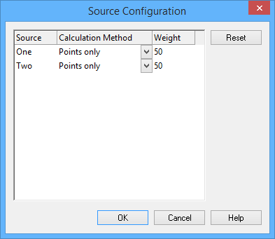
Advanced Options | Source Configuration | Click Browse (...) to configure the two sources. The Source Configuration dialog box is displayed. For each source, you set the following properties: • Calculation Method: Select from: • Points only: Point and line features on the source will be treated as points. Only the vertices of the lines will be considered. • Lines as interpolated points: Any line on the source will be interpolated with points at the interpolation interval specified in the dialog box. Use this if you want to consider both normal baseline points and straight baselines or use the normal baseline points algorithm on straight baselines. • Lines as continuous segments: All lines on the source will be treated as continuous geodetic segments. This is not available if the source contains points. Both sources must contain only lines. • Weight: This is used for the equiratio method. The equidistant line is weighed preferentially towards one shore or the other.The weighted value is the ratio of the two values. For example, if source one is weighted as 3 and source two as 5, the ratio will be 3:5. Enter as an integer greater than 0. |
Construction Lines | Draw the construction lines joining the contributing points of the two sources to the turning points on the median line. Type an acronym directly or select an option from the list. The list contains the following options: • A list of recent objects, if any: Select this to reuse a previous object. • Template: Select a template using the Select Template dialog box. • Objects: Define the feature acronym and attributes using the Select Object dialog box. | |
Advanced Options (cont.) | Contributing Points | Draw the contributing points using a specific object representation. Type an acronym directly or select an option from the list. The list contains the following options: • A list of recent objects, if any: Select this to reuse a previous object. • Template: Select a template using the Select Template dialog box. • Objects: Define the feature acronym and attributes using the Select Object dialog box. |
Limit | Distance at which to extrapolate the median line using the ending or extreme points from both sources. If used, this must be a positive numeric value. The last value set is remembered. | |
Interpolation Interval | The interval of interpolation between points for lines on the sources. This is used for each input source only when the source configuration method is Lines as interpolated points. Type a value. The default is 10 nautical miles, but the value will display using the Distance setting in the Display Units Options tab. The last value set is remembered. | |
Reverse Direction | This option is used in the case of adjacent countries where the equidistance line can be calculated in the seaward or landward direction. The Reverse Direction option is used to change the direction in which the equidistance line is calculated to ensure that the seaward direction is obtained • True: Reverse the direction in which the equidistant line is calculated. • False: Use the default direction for calculation of the equidistant line. If the resulting line is to landward, undo the command and try again with this option enabled. |
The default values for these settings are displayed using the Display Units settings in Options. |
Procedure
1. Select the Median Lines command.
The Median Line dialog box is displayed.
2. Set any necessary options.
3. Click OK.