Menu | Tools > Coverages > Modify > Select Points |
Pop-up | coverage > Tools > Select Points (Layers window) |
Process | Classify Points for Cartography |
The Select Points command is used to assign a classification value of Selected to points in a point cloud in order to identify the best points to use for cartographic purposes. Prior to running this command, the Suppress Points command can be run to assign a classification of Suppressed to undesirable points, ensuring that those points do not get classified as Selected.
This command provides four separate processes, which are intended to be run in a sequence to complete the classification process. The process to be run is selected from the dialog box displayed when the command is launched. The processes are listed in the dialog box in the order that they should be run. The four processes are explained below.
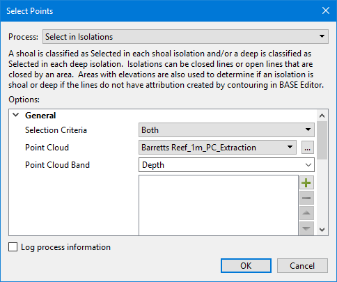
• Select in Isolations: This process classifies points in isolations as Selected based on the rule being applied. For each deep isolation, the deepest unclassified point will be classified as Selected and/or for each shoal isolation, the shoalest unclassified point will be classified as Selected. Isolations are designated by closed lines or open lines that are closed by an area. If these lines do not have isolation type attribution, areas with elevations will be used to determine if an isolation is a shoal or a deep.
• Select Critical Shoals: This process classifies critical shoal points as Selected. A critical shoal is a shoal point that is surrounded by deeper points.
• Select Significant Points: This process classifies points as Selected based on how far they are away from a reference surface. The reference surface is calculated from features with elevation attribution and other points already classified as Selected.
• Select Background Points: This process is used to identify shoal and deep points remaining unclassified after all other processes in this command have been run. The process looks for shoal or deep points that are not within a certain distance of any Selected point, and then classifies the found point as Selected.
As each process is run, Selection_State and Selection_Rule bands are added to the input point cloud. These bands are populated according to the classification results and are updated with each process run. If the bands already exist in the input point cloud, only unclassified points are updated by the process. When all processes have been run, the contents of these bands represent the best points in the point cloud for cartographic use.
Related commands:
Interface
The Select Points command uses the following dialog box.
Option | Description |
|---|---|
Common Options | |
Process | The classification process to be run. The options displayed in the dialog box will change based on the process selected. 1. Select a process from the drop-down list. |
Point Cloud | The input point cloud containing the source points in CSAR format. When the process is run, Selection_State and Selection_Rule bands will be added to this point cloud. If a point cloud is open in the application when the command is launched, that point cloud will be selected by default. If more than one point cloud is open, the active point cloud (highlighted in the Layers window) will be selected. The drop-down list is populated with all open point clouds. 1. Select a point cloud from the drop-down list or click the browse button (...) to launch the Open file dialog box. 2. Navigate to the relevant point cloud. 3. Click Open. |
Point Cloud Band | The band within the input point cloud that contains the values to be used in calculations. The primary elevation band of the input point cloud is selected by default. 1. Type the name of the relevant band in the field. |
Log process information | Create a log file containing the options specified when the process was run. The location of the log file is determined by the Logs setting in Tools > Options > Files and Folders. 1. Click the check box to enable the option. |
Select in Isolations Options | |
Selection Criteria | The algorithm(s) used to select points in the point cloud. You can choose to either classify the shoalest points, the deepest points or both. 1. Select an option from the drop-down list. |
Contours and Depth Areas | The feature objects that will be used to identify isolations. Isolations can be closed lines or open lines closed by the boundary of an area with an elevation attribute. Areas with elevations are required to determine whether an isolation is a shoal or a deep if the source contours do not have the isotyp attribution created in BASE Editor. Feature objects can be specified from multiple file sources if needed. If multiple sources are specified, the algorithm will identify isolations from the files in the order that the files are listed in the dialog box. 1. Click the Plus button 2. Navigate to the file containing the relevant feature objects. 3. Click Open. 4. Repeat for each feature source file to be included. 5. [Optional] Use the Up and Down Arrow buttons |
Rule Name for Deep Isolations | The rule name applied when classifying points in deep isolations. This name will be added as a classification value in the String Table dialog box when launched from the Selection_Rule band. 1. Click the check box to enable the option. 2. Type a rule name in the field. |
Rule Name for Shoal Isolations | The rule name applied when classifying points in shoal isolations. This name will be added as a classification value in the String Table dialog box when launched from the Selection_Rule band. 1. Click the check box to enable the option. 2. Type a rule name in the field. |
Select Critical Shoals Options | |
Minimum Distance from Selection | The minimum distance between points classified as Selected. The Coefficient fields can be used to define a constant radius or depth-dependent radii. The following types of radii can be used: • Fixed radius = <Coefficient 1> • Linear radius = <Coefficient 1> + <Coefficient 2> * depth • Quadratic radius = <Coefficient 1> + <Coefficient 2> * depth + <Coefficient 3> * depth^2 All selection algorithms skip over a point if any Selected points are within the area of influence of that point. 1. Enter a radius value and select a unit of measure for Coefficient 1. 2. Click the check box to populate Coefficient 2 and Coefficient 3. 3. Enter scaling factors for Coefficient 2 and Coefficient 3. Note: Both "Coefficient 2 * depth" and "Coefficient 3 * depth * depth" are interpreted as a distance with the same unit as Coefficient 1. |
Map Scale for Minimum Distance | A number specifying the scaling to apply to the radius coefficient values (1:scale). If the distance specified represents distance on the ground, then a scale of 1 is used. Otherwise, the map scale representing the distance must be specified. For example, a scale of 1000 would mean that the Radius Coefficient 1 value represents the minimum distance between features on a map at 1:1000 scale; the radius would then be a value like 10mm. 1. Enter a value in the field. |
Vertical Tolerance Percentage | A number specifying a percentage of depth to consider as significant. This is the value that the surrounding points have to be deeper than the given point for it to be considered as a significant shoal. The valid values are 0 to 100. 1. Enter a value in the field. |
Area Features to Limit Classification | The area features that define the boundary for classification. If specified, the algorithm will only consider points with these areas. If the specified feature file does not contain area features, then no points in the input are considered for classification. If this option is not specified, all points in the input point cloud are considered. When enabled, the field is populated with all feature files open in the application. 1. Click the check box to enable the option. 2. In the field, click the check box of each feature file to be applied. |
Rule Name | The rule name used when classifying points in critical shoals. This name will be added as a classification value in the String Table dialog box when launched from the Selection_Rule band. 1. Enter a name in the field. |
Select Significant Points Options | |
Selection Criteria | The criteria by which points will be selected, based on their physical location in relation to a reference surface. The reference surface is created from the specified reference features and all other points in the point cloud already classified as Selected. The order that points are considered for classification is based on the selected criteria setting. A point will be classified as Selected if there are no previously Selected points nearby. |
Reference Features with Elevations | The source file containing features with elevations, such as contours and points, that will be used in the creation of the reference surface. The list of available feature sources is populated with all feature files open in the application. 1. Click the check box of each feature file to include in the reference surface. |
Minimum Distance from Selection | The minimum distance between points classified as Selected. The Coefficient fields can be used to define a constant radius or depth-dependent radii. The following types of radii can be used: • Fixed radius = <Coefficient 1> • Linear radius = <Coefficient 1> + <Coefficient 2> * depth • Quadratic radius = <Coefficient 1> + <Coefficient 2> * depth + <Coefficient 3> * depth^2 All selection algorithms skip over a point if any Selected points are within the area of influence of that point. 1. Enter a radius value and select a unit of measure for Coefficient 1. 2. Click the check box to populate Coefficient 2 and Coefficient 3. 3. Enter scaling factors for Coefficient 2 and Coefficient 3. Note: Both "Coefficient 2 * depth" and "Coefficient 3 * depth * depth" are interpreted as a distance with the same unit as Coefficient 1. |
Map Scale for Minimum Distance | A number specifying the scaling to apply to the radius coefficient values (1:scale). If the distance specified represents distance on the ground, then a scale of 1 is used. Otherwise, the map scale representing the distance must be specified. For example, a scale of 1000 would mean that the Radius Coefficient 1 value represents the minimum distance between features on a map at 1:1000 scale; the radius would then be a value like 10mm. 1. Enter a value in the field. |
Vertical Tolerance Percentage | A number specifying a percentage of depth to consider as significant. This is the value that the surrounding points have to be deeper than the given point for it to be considered as a significant shoal. The valid values are 0 to 100. This setting is mandatory if Vertical Tolerance is not specified. If both Vertical Tolerance and Vertical Tolerance Percentage are specified, both values are calculated for each input point, and the largest of the two values is used. 1. Enter a value in the field. |
Vertical Tolerance | A number and unit specifying the distance from the reference surface to consider as significant. Points less than the vertical tolerance away from the reference surface will be ignored. This setting is mandatory if Vertical Tolerance Percentage is not specified. If both Vertical Tolerance and Vertical Tolerance Percentage are specified, both values are calculated for each input point, and the largest of the two values is used. 1. Click the check box to enable the option. 2. Enter a distance value and select a unit of measure. |
Area Features to Limit Classification | The area features that define the boundary for classification. If specified, the algorithm will only consider points with these areas. If the specified feature file does not contain area features, then no points in the input are considered for classification. If this option is not specified, all points in the input point cloud are considered. When enabled, the field is populated with all feature files open in the application. 1. Click the check box to enable the option. 2. In the field, click the check box of each feature file to be applied. |
Rule Name for Farthest from Reference | The rule name used when classifying based on farthest from reference. This name will be added as a classification value in the String Table dialog box when launched from the Selection_Rule band. 1. Click the check box to enable the option. 2. Enter a name in the field. |
Rule Name for Farthest Above Reference | The rule name used when classifying based on farthest above reference. This name will be added as a classification value in the String Table dialog box when launched from the Selection_Rule band. 1. Click the check box to enable the option. 2. Enter a name in the field. |
Rule Name for Farthest Below Reference | The rule name used when classifying based on farthest below reference. This name will be added as a classification value in the String Table dialog box when launched from the Selection_Rule band. 1. Click the check box to enable the option. 2. Enter a name in the field. |
Select Background Points Options | |
Selection Criteria | The criteria used to identify points that will be classified as Selected. Choose whether the shoalest or deepest points will be classified when no previously Selected points are nearby. |
Minimum Distance from Selection | The minimum distance between points classified as Selected. The Coefficient fields can be used to define a constant radius or depth-dependent radii. The following types of radii can be used: • Fixed radius = <Coefficient 1> • Linear radius = <Coefficient 1> + <Coefficient 2> * depth • Quadratic radius = <Coefficient 1> + <Coefficient 2> * depth + <Coefficient 3> * depth^2 All selection algorithms skip over a point if any Selected points are within the area of influence of that point. 1. Enter a radius value and select a unit of measure for Coefficient 1. 2. Click the check box to populate Coefficient 2 and Coefficient 3. 3. Enter scaling factors for Coefficient 2 and Coefficient 3. Note: Both "Coefficient 2 * depth" and "Coefficient 3 * depth * depth" are interpreted as a distance with the same unit as Coefficient 1. |
Map Scale for Minimum Distance | A number specifying the scaling to apply to the radius coefficient values (1:scale). If the distance specified represents distance on the ground, then a scale of 1 is used. Otherwise, the map scale representing the distance must be specified. For example, a scale of 1000 would mean that the Radius Coefficient 1 value represents the minimum distance between features on a map at 1:1000 scale; the radius would then be a value like 10mm. 1. Enter a value in the field. |
Features to Limit Calculations | The features that define the boundary for classification. If specified, the algorithm will only consider points with these areas. If the specified feature file does not contain area features, then no points in the input are considered for classification. If this option is not specified, all points in the input point cloud are considered. When enabled, the field is populated with all feature files open in the application. 1. Click the check box to enable the option. 2. In the field: • Click the check box of each feature file to be applied, or • Click the browse button and navigate to the relevant feature file. |
Apply Buffer to Limiting Features | This option is used create expanded buffered area features around the input features to restrict the calculations to only be applied around these features. 1. Click the check box to enable this option. |
Buffer Distance | The distance around/outside features to be considered as part of the input features if applying a buffer. 1. Enter a value and select a unit of measure for the buffer distance. |
Rule Name for Shoal Point Selection | The rule name used when classifying shoal points iteratively. This name will be added as a classification value in the String Table dialog box when launched from the Selection_Rule band. 1. Click the check box to enable the option. 2. Enter a name in the field. |
Rule Name for Deep Point Selection | The rule name used when classifying deep points iteratively. This name will be added as a classification value in the String Table dialog box when launched from the Selection_Rule band. 1. Click the check box to enable the option. 2. Enter a name in the field. |
Procedure
1. Open the point cloud for which points are to be classified as Selected.
2. Open any feature files containing feature objects that will be used as elevation and boundary references.
3. Select the Select Points command.
The Select dialog box is displayed.
4. Select the relevant process from the Process drop-down list, keeping in mind that the processes should be run in the order that they are listed in the drop-down list.
5. Define all necessary options.
6. Click OK.
A Processing dialog box is displayed to show the progress.
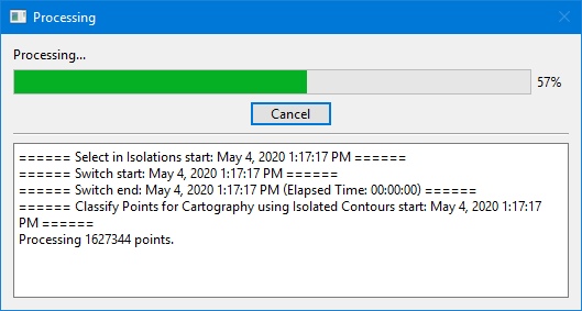
7. When processing reaches 100%, click Close to close the dialog box.
Selection_Rule and Selection_State bands should now be present in the point cloud, populated with the points that have been classified as Selected.
The command can now be run again using the next process in the list until all processes have been run.
 to launch the Open file dialog box.