Tool | CZMIL > Optimize Reflectance data and apply (Tools window) |
The Optimize Reflectance Data and Apply process model runs the processed CZMIL data through an algorithm to radiometrically balance all the Shallow channels and to get an optimized version of the reflectance. These values can then be applied to the data by georeferencing the CZMIL points and outputting a new reflectance image or surface.
CARIS Batch process: Optimize CZMIL Reflectance
Note: The Optimize CZMIL Reflectance process itself does not georeference the data or generate outputs, the process model must be used to achieve those outcomes. |
Interface
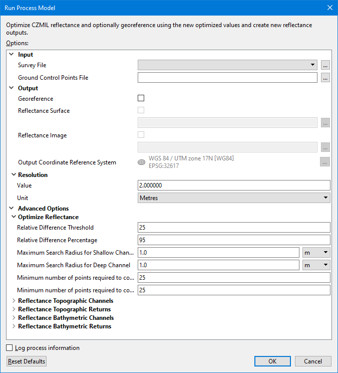
The options in this process model include:
Option | Description | |
|---|---|---|
Input | Survey File | The name and location of the survey file containing the survey lines of CZMIL data. If a survey file is open in the application, a drop-down list is also provided for this option. The drop-down list allows a survey layer open in the application or the current selection (if a survey line is selected) to be used as the input survey. 1. Click the browse button (...) to launch an Open file dialog box. 2. Navigate to the relevant file. 3. Click Open. |
Ground Control Points Files | A CSV file containing ground control points, which are reflectance measurements of targets like road, grass, bare earth, tarmac, etc. normally collected using a hand-held spectrometer at Green wavelength and the corresponding geographical locations. The measurements are used to optimize CZMIL reflectance. The ground control points file contains 4 columns of reflectance measurements and their geographical positions in the format “ID, Latitude, Longitude, Reflectance”. 1. Click the browse button (...) to launch an Open file dialog box. 2. Navigate to the relevant file. 3. Click Open. | |
Output | Georeference | Enable this option to run the Georeference CZMIL Points process while applying optimization. This process applies roll, pitch, and heading corrections to generate a point cloud data referenced to ellipsoid height. See Georeference CZMIL Datafor information on this process. |
Reflectance Surface | Enable this option to generate a reflectance surface while applying optimization. A name and location must be specified for the resulting .csar surface. By default, the file will be created using the same name and location as the survey file. 1. Click the check box to enable the option. 2. Click the browse button (...) to launch an Save file dialog box. 3. Specify a name and location for the surface. 4. Click Save. This option is only available if the Georeference option is enabled. | |
Reflectance Image | Enable this option to generate a reflectance image while applying optimization. A name and location must be specified for the resulting image file. By default, the file will be created using the same name and location as the survey file. 1. Click the check box to enable the option. 2. Click the browse button (...) to launch an Save file dialog box. 3. Specify a name and location for the image file. 4. Click Save. This option is only available if the Georeference option is enabled. | |
Output Coordinate Reference System | The coordinate reference system (CRS) that will be used if the data will be georeferenced and output to an image or a surface. 1. Click the Browse button (...) to launch the Select Coordinate Reference System dialog box. 2. Select a CRS from the list. 3. Click OK. This option is only available if the Georeference option is enabled. | |
Resolution | Value | The ground resolution that will be used to create the reflectance output. 1. Type a value in the field. |
Unit | The unit of measure that will be used for the resolution value used to generate the reflectance output. 1. Select a unit of measure from the drop-down list. | |
Optimize Reflectance Options | Relative Difference Threshold | The minimum required relative difference percentage between the ground control points and CZMIL measured reflectance. The default value is 25. |
Relative Difference Percentage | A number specifying the total minimum required relative difference percentage between the ground control points and CZMIL measured reflectance. The default value is 95% | |
Maximum Search Radius for Shallow Channel | The maximum spatial distance allowed between Shallow channel points and ground control points. The default value is 1m. | |
Maximum Search Radius for Deep Channel | The maximum spatial distance allowed between Deep channel points and ground control points. The default value is 1m. | |
Minimum number of points required to compute relative difference percentage (Shallow Channel) | The minimum number of qualified Control/Check points required for the processing of the Shallow channel. The default value is 25. | |
Minimum number of points required to compute relative difference percentage (Deep Channel) | The minimum number of qualified Control/Check points required for the processing of the Deep channel. The default value is 25. | |
Topography Options | The topography data channels and data returns in the survey data from which values will be read when generating the output image. 1. Click to populate the check box of each channel to be included. 2. Click to populate the check box of each return to be included. | |
Bathymetry Options | The bathymetry data channels and data returns in the survey data from which values will be read when generating the output image. 1. Click to populate the check box of each channel to be included. 2. Click to populate the check box of each return to be included. | |
Log process information | Create a log file containing the options specified when the process was run. The location of the log file is determined by the Logs setting in Tools > Options > Files and Folders. 1. Click the check box to enable this option. | |
Procedure
1. Double-click the Optimize CZMIL Reflectance process model in the Tools window.
The Run Process Model dialog box is displayed, populated with the Optimize CZMIL Reflectance process model.
2. Click the Survey File browse button (...) and navigate to the relevant file.
3. Click the Ground Control Points File browse button (...) and navigate to the relevant file.
4. Define the Optimize Reflectance Options settings.
5. Define any other necessary options.
6. Click OK.
A progress dialog box is displayed providing information about the data being optimized. Additional information is also provided via messages in the Output window.