Tool | CZMIL > 04 - Compute/Apply CZMIL Calibration (Tools window) |
The Compute/Apply CZMIL Calibration process model can be used to compute calibration on CZMIL data and then apply it using the Georeference CZMIL Points process. This calibration is used to apply corrections to the data to compensate for misalignments of sensors and flightlines during data acquisition.
CARIS Batch process:
Interface
The options in this process model include:
Option | Description |
|---|---|
Survey File | The name and location of the survey file containing the survey lines of CZMIL data. If a survey file is open in the application, a drop-down list is also provided for this option. The drop-down list allows a survey layer open in the application or the current selection (if a survey line is selected) to be used as the input survey. 1. Click the browse button (...) to launch an Open file dialog box. 2. Navigate to the relevant file. 3. Click Open. |
Compute Calibration for CZMIL data | Enable this option to compute the calibration values for the selected survey file. The calibration values can be applied now or at a later time. 1. Click the check box to enable this option. |
Apply Calibration through Georeference CZMIL Points | Enable this option to apply calibration values to the selected survey file by running the Georeference CZMIL Points process. The calibration values to be applied can be from a previous computation or from the current run of the process model. 1. Click the check box to enable this option. |
Lidar Corrections | The corrections to be applied during calibration. The options include: • Boresight - Adjusts the misalignment (Boresight) angles between IMU and Sensor. This correction should be applied whenever the system is re-installed or components are replaced. • Production - Adjusts the trajectory to correct for misalignments between flightlines. This correction should be applied to improve matching of project data. • Bathy LookUp Table - Adjusts the bathy look-up-table coefficients by comparing CZMIL data against ground control points (GCP). This process requires the Ground Control Points File option to be populated with a GCP file in ASCII format. • Boresight Plus Range In Air: Adjusts the misalignment (Boresight) angles between IMU and Sensor, along with Range scale and offsets. This correction should be applied whenever the system is re-installed or components are replaced. This process requires the Ground Control Points File option to be populated with a GCP file in ASCII format. • Sensor Calibration - Adjusts the intrinsic sensor calibration parameters, including angular and range corrections between channels. This option should only be used after sensor repairs or when advised by Teledyne. This process requires the Ground Control Points File option to be populated with a GCP file in ASCII format. |
Ground Control Points File | A file containing ground control points. LMS uses ground control points to adjust the calibration parameters during the calibration process. LMS accepts control points given with their IDs and standard deviations. The control points should be in an ASCII file as a list of coordinates. Each control point should be written on a separate line. LMS skips lines starting with the # symbol. There are several supported formats for an ASCII file with a set of control points: • 3 columns: X, Y, Z • 4 columns: ID, X, Y, Z • 6 columns: X, Y, Z, Std_Dev (X), Std_Dev (Y), Std_Dev (Z) • 7 columns: ID, X, Y, Z, Std_Dev (X), Std_Dev (Y), Std_Dev (Z) |
Log process information | Create a log file containing the options specified when the process was run. The location of the log file is determined by the Logs setting in Tools > Options > Files and Folders. 1. Click the check box to enable this option. |
Procedure
1. Double-click the Compute/Apply CZMIL Calibration process model in the Tools window.
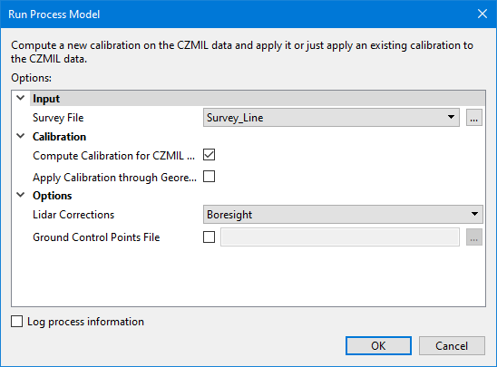
The Run Process Model dialog box is displayed, populated with the Compute/Apply CZMIL Calibration process model.
2. Navigate to the relevant Survey File.
3. Enable the Compute and/or Apply option.
4. Select the Lidar Corrections to be computed.
5. Navigate to the relevant Ground Control Points File, if needed.
6. Click OK.
A progress dialog box is displayed providing progress information as the calibration is computed and/or applied. Similar information is also reported in the Output window.
7. When finished, click the Close button to close the dialog box and complete the process.