The master file (ih_master.txt) is a text file containing feature codes and instructions for plotting features on a chart. The master file is used with paper charts and CARIS DES charts. The file is sorted alphabetically by feature code.
The master file controls the appearance of map data. It contains instructions for:
• patterning lines
• combining symbols to form composite symbols
• presenting text
• masking overlapping features
The master file consists of a number of main records and subrecords. Each feature code described in the master file is represented by one main record and, optionally, one or more subrecords. Each main record or subrecord occupies one line of text which can be up to 80 characters in length.
A main record contains 13 fields. Field 4 of a main record contains comments.
If field 2 contains the letter L, S, T, or M, it is a subrecord, which contains four fields. Field 4 of a subrecord contains instructions.
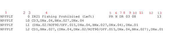
The field numbers are on the first line and the field names on the second line. The main record is on the third line; subrecords describing how the line is patterned are on subsequent lines.
The following table describes the fields in the file.
This table describes the function of each field in a main record.
Field | Start-End | Field | Description |
|---|---|---|---|
1 | 1-12 |
| Feature code, containing up to 12 characters (letters, numbers, underscore). |
2 | 13-13 | This field must be blank in a main record. | |
3 | 14-14 | For a main record, the value is always 0. | |
4 | 16-51 |
| A brief description of the feature code. |
5 | 53-54 |
| (For applicable plotters only). Colour Separation. The Colour Code in which the feature will be plotted, where: • GY = grey • BK = black • BN = brown • BL = blue • PR = purple • BG = black/grey • OR = orange • AL = all colours |
6 | 56-56 |
| A peel coat flag for photo-plotters only, where: • S = symbolized • U = unsymbolized • N = not used |
7(a) | 58 |
| Specification to draw or flash features, where: • F = flashed • D = drawn |
7(b) | 59 |
| End points for lines on photoplotters: • R = rectangular • D = dotted (rounded) |
8 | 61-62 |
| Case numbers associated with plotting instructions, where: • 00 = specification of an unpatterned feature that will be refused by the patterning routine • 01 = plotting of an unpatterned feature with simple lines that can be patterned later • 02=plotting of a feature with simple lines that will be patterned by the patterning routine • 03 =use of plotting instructions in the line (L) subrecord • 04 = sounding • 05 = spot height • 06 = compass rose • 07 = text • 08 = point symbols • 09 = measured distance • 10 = foot bridge • 11 = viaduct • 12 = bascule • 13 = lift bridge • 14 = swing bridge • 15 = literal bridge (general) • 16 = sector light |
9 | 64-65 |
| Line weight. The line thickness of the feature, expressed in thousandths of an inch. The default value is 05 (0.005 inches). |
10 | 67-69 |
| Disk/Symbol. The reference to a disk and symbol number for flashed symbols (applicable to photoplotters only). |
11 | 71-71 |
| A magnification factor. The value is from 0 to 9 for symbols, where 0 or 1 is normal size. |
12 | 73-74 |
| Not in use. |
13 | 76-80 |
| Data Code: The type of data that may be categorized by up to four codes, where: • 1 = Stream digitizing, smooth lines (CARIS-generated) • 3 = Point-to-point lines (operator-generated) • 4 = dashed lines • 7 = text • 8 = symbols • A = soundings • B = spot height |