Line Pattern Examples | |
| Example 1 is a dashed line. EXAMPLE01 0 Symbolization example 01 BK N DR 03 05 13 EXAMPLE01 L0 DNX.25 (BFX.25, DNX.25) This generates a line that begins with a dash of • a blank of • a dash of |
| Example 2 illustrates the placing of symbols between dashes. EXAMPLE02 0 Symbolization example 02 BK N DR 03 05 13 EXAMPLE02 L0 DNX.2,NMF0.01(KOP,BFX.125,SYO,BFX.125,DNX.2) This generates a line beginning with a dash • a space of • a symbol • a space of • a dash of Note that the KOP (symbol change OP) command defines the symbol to be used; it does not actually output a symbol. The SYO command outputs the symbol. |
| Example 3 is like example 2 except that the symbols are placed midway between the points. To achieve this, the pattern for the symbol must occur after the definition of the segments on which it will be centred. The line pattern definition becomes: EXAMPLE03 0 Symbolization example 03 BK N DR 03 05 13 EXAMPLE03 L0 DNX.125,NMF0.01(KOP,BNX.125,SYM,DNX.125)DNX.001 |
| Example 4 uses an embankment symbol. EXAMPLE04 0 Symbolization example 04 BK N DR 03 05 13 EXAMPLE04 L0 (KEM, BNX.05, SYM) DNX.01 The definition uses the symbol change command (KEM)) which changes the current symbol ID to EM (embankment symbol). The pattern consists of the following: • a blank which is larger than a single symbol (BNX.05), • an embankment symbol (SYM), and • a short pattern specifying normalized dashes, |
| Example 5 is identical to example 4, except that the embankment symbol is rotated (ROT) 180 degrees which flips the symbol over. EXAMPLE05 0 Symbolization example 05 BK N DR 03 05 3 EXAMPLE05 L0 (KEM, BNX.05, SYM/ROT180) DNX.01 |
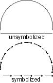
| Example 6 uses the AG (arc generate) command. EXAMPLE06 0 Symbolization example 06 BK N DR 03 05 13 EXAMPLE06 L0 BNX.01, AGM360:0 (BNX.001) DNX.01 The beginning blank ( |
| Example 7 does not include a begin pattern. EXAMPLE07 0 Symbolization example 07 BK N DR 03 05 13 EXAMPLE07 L0 (BNX.03, DNX.08, KZPDOT020, SYO) DNX.01 The repeat pattern includes: • a blank • a dash • the symbol change command ( • a symbol placed at the end of the preceding dash (SYO). The symbol command (SYO) not only generates a symbol but gives the direction of the pattern. |
| Example 8 places a symbol at each significant point. EXAMPLE08 0 Symbolization example 08 BK N DR 03 05 13 EXAMPLE08 L0 KUTPY,PAS/OFF.02,BFX.001,SYO, BNX.02(BNX.5,SYX)DNX.01 The definition contains a beginning pattern with the following components: • KTW: changes the symbol ID to TW (a pylon) • PAS/OFF.02 - outputs the unsymbolized line and offsets it by • BFX.001 - inserts a very small blank, necessary to place the centre of the following pylon symbol at, or as near as possible to, the beginning of the line • SYO - places a pylon symbol • BNX.02 - leaves a normalized blank The repeat pattern contains the following: • BNX.5 - inserts a normalized blank which allows for spacing between the pylon symbol and the PASsed line which is to follow • SYX - indicates that a symbol will be placed at the end of the line only The short pattern specifies a normalized dash |
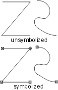
| Example 9 uses rotated dashes. EXAMPLE09 0 Symbolization example 09 BK N DR 03 05 13 EXAMPLE09 L0 PAS,BNx.02 (DNx.04/OFF.02/ROT90/BNx.02) DNx.01 The pattern definition contains a beginning pattern with the following components: • PAS - outputs the unsymbolized line • BNX.02 - places a blank (which can be normalized) with length The repeat pattern contains: • DNX.04/OFF.02/ROT90 - places a dash which is offset by half a dash length and rotated by 90 degrees, causing the end of the dash to be perpendicular to and just touching the passed line • BNX.02 - a blank which serves as a spacer between successive dashes |
| Example 10 outputs a single line with three different patterns. EXAMPLE10 0 Symbolization example 10 BK N DR 03 05 13 EXAMPLE10 L0 TOL0.0,:1:4,LSS:3,BNX.02(DNx.04,BNx.02 DNx.01) The pattern definition contains a beginning pattern with the following components: • TOL0.0 - sets the tolerance for checking significant points to 0 degrees, which causes all points on a line to be treated as significant. • :1:4) - specifies that line segments 1 (from point 1 to point 2) and 4 (from point 4 to point 5) are to be output literally, i.e. in their unsymbolized form. • LSS:3 - specifies that line segment 3 (from point 3 to point 4) is to be output as blank space. The repeat pattern creates a line with dashes |
| Example 11 uses a series of dots varying in size from large to small (K0D,K8D,K5D). The first dot is on the line; the second and third are shifted to the right in the direction of the line and offset from the previous. The result is a stepping effect of dots. EXAMPLE11 0 Symbolization example 11 BK N DR 03 05 13 EXAMPLE11 L0 BNx.01(KZPDOT012,SYM,BNx.03,KZPDOT026,SYM/OFF .03, EXAMPLE11 L1 BNx.03,KZPDOT020,SYM/OFF.06,BNx.01) DNx.01 The begin pattern specifies a blank • KOD - changes current symbol to the one with symbol id OD (a dot) • SYM - places the current symbol (dot) on the line • BNX.03 - leaves a blank The remainder of the repeat pattern is similar, but with two larger dot symbols, each with an associated offset. |
| Example 12 uses rotated dashes to create a pattern of crosses. EXAMPLE12 0 Symbolization example 12 BK N DR 03 05 13 EXAMPLE12 L0 BNX.03(DNX.04,DNX.04/ROT90,DNX.04,BNX.03) DNX.01 The pattern consists of: • a beginning pattern which specifies a blank • a repeat group of 3 dashes of equal length (.04 inches) with the middle dash rotated by 90 degrees (ROT90) This gives the appearance of crosses separated by blanks. |
| Example 13 has no beginning pattern. EXAMPLE13 0 Symbolization example 13 BK N DR 03 05 13 EXAMPLE13 L0 (KW176,BFx.048,SYM) DNx.01 The repeat pattern consists of: • KW176 - changes the current symbol to that with symbol id W176 (the tilde character). • BFx.048 - places a blank of fixed length • SYM - places the tilde symbol on the line The short pattern places consecutive dashes |
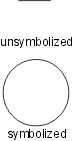
| Example 14 generates a circle. EXAMPLE14 0 Symbolization example 14 BK N DR 03 05 13 EXAMPLE14 L0 TOL0.0,LEX.42,DIS,LSS:2 (BFx.0004,AGM360:0 EXAMPLE14 L1 /RAD.11,BFx.31,AGO125:90/RAD.4/OFF-.4, EXAMPLE14 L2 AGO235:270/RAD.4/OFF.4,BNx.01) DNx.01 The beginning pattern consists of: • TOL0.0 - sets the tolerance for checking significant points to 0.0 • LEX.42 - extends each line segment by • DIS - discards the unused portion of any line segment. • LSS:2 - skips the line segment from point 2 to 3 The repeat pattern consists of: • BFX.0004 - place a small fixed blank • AGM 360:0/RAD.11 - generate a circle with radius • BFX.31 - place a fixed blank • AGO125:90/RAD.4/OFF-.4 - generates an arc with radius • AGO235:270/RAD.4/OFF.4 - generates an arc with radius • BNX.01 - places a blank |
| Example 15 includes: • a beginning pattern of two dashes separated by a blank • a repeat pattern containing a dash rotated by 90 degrees and offset by This creates a series of T-shapes along the line, similar to the international boundary symbol, except that the second dash is offset by half the dash size so that the second dash is centred between, and perpendicular to, the first and third dashes. The pattern begins with a dash and a blank so that the half dash allows for proper corners. The right-hand version of this pattern is identical except that the offset of the second dash is negative. EXAMPLE15 0 Symbolization example 15 BK N DR 03 05 13 EXAMPLE15 L0 DNx.03,BNx.03,DNx.03 (DNx.03/ROT90/OFF.015, EXAMPLE15 L1 DNx.03,BNx.03,DNx.03,) DNx.01 |
| Example 16 includes a repeating sub-pattern. This is similar to example 15, except that the dashes used to create the T-shape are enclosed in square parentheses to indicate they are part of a sub-pattern which is to be repeated 2 times. The pattern begins with a dash, a blank and another dash to allow for half dashing. A repeating sub-pattern of two T- shapes is then produced, followed by a third T-shape created separately. This is done to accommodate the symbols and to guarantee that the final pattern is a mirror image of the beginning pattern. After the third T-shape, the current symbol is changed to KMPAB. A blank of fixed length is inserted followed by a blank in which to place the symbol (SYM). The symbol is rotated -360 degrees to ensure that the symbol is always vertical to the base of the map. The remainder of the pattern definition is a repeating sub-pattern of the T-shape, except that two rather than three T-shapes are generated. The right-hand version of this feature has a negative offset. EXAMPLE16 0 Symbolization example 16 BK N DR 03 05 13 EXAMPLE16 L0 DNx.03,BNx.03,DNx.03 ([2;DNx.03/ROT90/OFF.015, EXAMPLE16 L1 DNx.03,BNx.03,DNx.03],DNx.03/ROT90/OFF.015, EXAMPLE16 L2 DNx.03,KMPAB,BFx.05,BFx.14,SYM/Rot-360,BFx.05 EXAMPLE16 L3 DNx.03,[2;DNx.03/ROT90/OFF.015,DNx.03,BNx.03, EXAMPLE16 L4 DNx.03]) DNx.01 |
| Example 17 (a bent arrow) contains: • no beginning pattern • a repeat pattern which includes an arrow offset by The arrow is generated from three digitized points with a width specified by the /OFF qualifier. The blank in the repeat pattern sets the length of the arrow. The width and length of the arrowhead are scaled in relation to the shaft width. Bent and curved arrows are generated using the AR2 and AR3 pattern commands, respectively. EXAMPLE17 0 Symbolization example 17 BK N DR 03 05 13 EXAMPLE17 L0 (AR2/OFF.05,BNx.001) DNx.01 |
| Example 18 (arrow feathered on both sides) contains: • LEX - ensures that symbolized line segments are at least • KAF - changes the current symbol to that with symbol id AF (an arrowhead) • DFX.03,SYM - places an arrowhead symbol at the midpoint of a fixed dash • DFX.34 - places a dash • [5; - the beginning of a repeating sub-pattern which will be repeated 5 times • DFX.02,DFX.04/ROT45/OFF.015/LWT.005 - places a dash which is both rotated and offset, representing the upper part of the feather; the line weight for the feather is set to • DFX.04/ROT315/OFF-.015/LWT.005] - places a dash representing the lower part of the feather; this completes the repeating sub-pattern • (BNX.001) - the repeat pattern is a blank with length EXAMPLE18 0 Symbolization example 18 BK N DR 03 05 13 EXAMPLE18 L0 LEX.5,KARROW,SYO/ROT180,DFx.34, EXAMPLE18 L1 [5;DFx.02,DFx.04/ROT45/OFF.015/LWT.005, EXAMPLE18 L2 DFx.04/ROT315/OFF-.015/LWT.005],(BNx.001) DNx.01 |
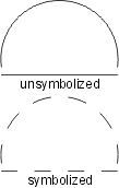
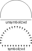
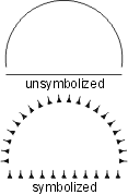
| The scalloped line uses the following line pattern definition: • TOL99.9 - used to eliminate all significant points • KSC - changes the symbol ID to SC • BNX.048 - leaves a blank • SYE - places the scallop symbol on the preceding blank; the symbol is sized so that it occupies the entire blank thus giving the appearance of a scallop. The symbol should be designed as shown. The repeat and short patterns are identical to the beginning pattern, except the symbol change command is not included. EXAMPLE19 0 Symbolization example 20 BK N DR 03 05 13 EXAMPLE19 L0 TOL99.9 KOP,BNx.048,SYE (BNx.048,SYE) BNx.048,SYE |
| Example 20 uses the /UPR qualifier, which causes the symbol to be upright with respect to the bottom of the map EXAMPLE20 0 Symbolization example 21 BK N DR 03 05 13 EXAMPLE20 L0 TOL999,DNX.05 KW124, EXAMPLE20 L1 (BNX.025,SYO/UPR/SIZ-2,BNX.025,DNX.05) |