Menu | Create > New Model Feature > Cross-section |
Tools |
|
Pop-up | Create New Cross-section (Model window) |
Menu | Create > New Model Feature > Cross-section |
Tools |
|
Pop-up | Create New Cross-section (Model window) |
Create a cross-section of a template by digitizing points at specified offsets from a defined central location and assigning depths.
A cross-section can be applied to alignments to automatically create a 3D model of a template and its surfaces.
Cross-sections are created with a prepackaged default initial state, or, if another cross-section was selected when you chose to create a new cross-section, the new cross-section will be a copy of the selected cross-section.
When a cross-selection is created or selected, the Cross-section window is opened automatically.
The view in this window can be adjusted using the same mouse controls as the Display window.
• Zoom: Click and drag to create a bounding box around the area that you want to zoom into, or scroll the middle-mouse wheel forward or reverse to zoom in and out.
• Pan: Middle-mouse click and drag to pan the display in the desired direction.
• Overview: Select the Overview command to display the full extents of the cross section after pan and zoom adjustments have been applied.
If the Cross-section window is undocked, the <F9> key must be used to select the Overview command. Selecting the Overview command from the menu or toolbar when an undocked window is active will automatically adjust the display in the most recently used main view rather the the undocked window. |
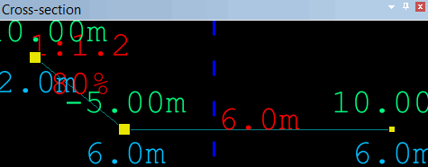
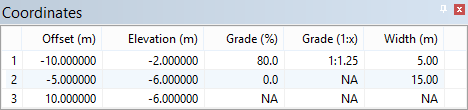
Every point in a cross-section has a depth as well as an offset from the location of the alignment, which is represented by a vertical blue dashed line (as seen in the image above). The following conventions are used to show information as clearly as possible:
• The offsets are displayed above the points, in green.
• The depths are displayed below the points, in blue.
• Information about the edges between points is displayed in red above the edges, for example, the depth of horizontal edges.
• The grade of sloped edges is displayed in red as a percentage and as a ratio.
Each of the settings mentioned above can be viewed and defined manually in the Coordinates window.
The number and position of points in the cross-section can be adjusted in the Display window.
Procedure
1. [Optional] Select an existing cross-section to use as a reference.
2. Select the New Cross-Section command.
The Cross-Section window is opened with the new cross-section displayed.
3. The following changes can be applied in the Display window as needed.
• To achieve a precise grade, right-click and select Edit Line > Snap to Grade and select the appropriate snapping mechanism. After choosing that setting, moving points will always preserve an appropriate slope value.
• The entire cross-section can be shifted by moving the mouse pointer over any of the edges, pressing the left mouse button and then dragging it to an appropriate location, and then releasing the button.
• An existing point can be deleted by selecting it, right-clicking, and then selecting the Edit Line > Delete option.
• One or more points can be moved at once by selecting them, pressing the left mouse button, dragging the cursor to an appropriate location, and then releasing the button. The <SHIFT> key can be used to select all points between two given points, and the <CTRL> key can be used to select any number of random points.
• Additional points can be added by pressing the <CTRL> key and clicking in the appropriate location on the cross section, or by right-clicking and choosing the Edit Line > Redigitize option.
Cross-sections cannot go back over themselves. |
