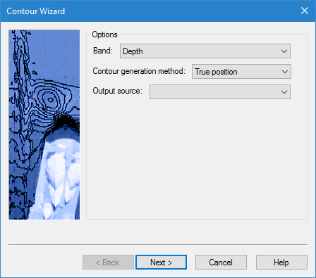
In this step of the Contour Wizard you specify the input and output settings for the contours.
One of the settings to be specified is the contour generation method, which defines how the contour boundaries will be created. The options available in the drop-down list are dependent on the selected source data.
• For a TIN layer, this option is disabled as the contour boundaries will automatically be built using the points in the TIN.
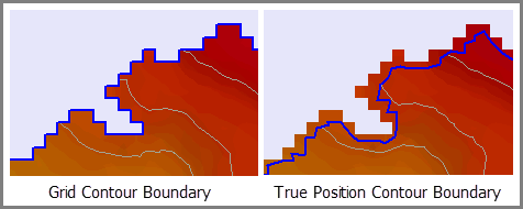
• For a band without true position data, contour boundaries can only be generated using the outer edges of the grid cells. In this case, Grid will be the only option in the list.
• For a band with true position data, contour boundaries can be created using either the true positions for the data, or the outer edges of the grid cells. In this case, True Position and Grid will both be available in the list.
Interface
The first step of the Contour Wizard uses the following dialog box.
Option | Description |
|---|---|
Band | The band of the source surface that will be used as the input height source for creating the contours. The options available are based on the bands present in the source surface. Select an option from the drop-down list. |
Contour generation method | The Contour generation method with which to create the contour lines. Select an option from the drop-down list. |
Output source | The feature layer that will be used to store the contour objects. The drop-down list is populated with all feature layers currently open in the application. Select an option from the drop-down list. |
Procedure
1. Select a band to use as the height source.
2. Select an option from the Contour generation method list.
3. Select a feature layer for storing the contours from the Output source list.
4. Click Next to go to the next step in the wizard.