![]() CARIS HPD Source Editor
CARIS HPD Source Editor
Menu | Tools > Limits and Boundaries > Densification |
Tool |
|
This command is only available if the Limits and Boundaries module is enabled. See Modules for further information |
Add vertices to edges at a given distance without altering the shape of the edge.
If the coastlines or low-water lines are geodetics or loxodromes, the points of the lines may not follow the curve. This command can be used to generate new lines with interpolated points that follow the curve at a given interval along line segments without altering the shape of the segments. The interval is restarted at the beginning of each line segment, and the original vertices and turning points of the line are preserved.
Densification is done according to line type. If a line or segment is a geodesic, it will be densified along the geodetic arc between its end points.
Related commands:
• • • • | • • • • |
Interface
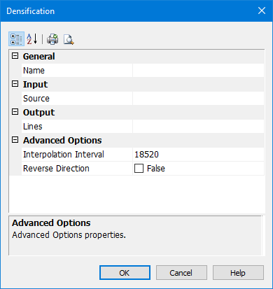
Group | Option | Description |
|---|---|---|
General | Name | The name of the layer that will contain the new line. Select from the list. This can be the same as the source layer. |
Input | Source | The input line or lines. By default, the most recently used source, if any, will be selected. Select from the list: • [blank line]: This will clear the text box. • Superselection: The superselected line, if any. This will not be available if no features are selected. • Selection: All selected lines, if any. This will not be available if no features are selected. • [list of layers]: All available layers. All lines in the layer will be used as source lines. It is recommended that you select a layer only if it contains suitable source lines and no other lines, such as a filtered layer that contains only coastlines. |
Output | Lines | The feature acronym and attributes of the output line. By default, the most recently used acronym, if any, will be selected. Type an acronym or select from the list: • [blank line]: This will clear the text box. • [recent objects]: A list of any recently used objects. • Templates: Displays the Select Template dialog box. See Using Templates with Limits and Boundaries for details. • Objects: Displays the Select Object dialog box. Select an acronym from the list of Feature Acronyms then define the attributes. |
Advanced Options | Interpolation Interval | The interval between points on the output line. Type a value. Units are based on the options settings. |
Reverse Direction | The line is densified based on the starting point and the direction in which it was digitized. Because the interval between added points restarts for each line segment, the location of the new points depends on the direction of the line. • False: The starting point of the line is not changed. • True: The starting point of the line is changed and the direction reversed. |
Toolbar:
Icon | Description |
|---|---|
| Categorized. Display the properties in their categories. |
| Alphabetical. Display the properties in alphabetical order. |
| Quick print. Prints the current settings of the dialog box. Displays a Print dialog box. |
| Print Preview. Displays the current settings of the dialog box. |
Procedure
1. Select the line.
2. Choose the Densification command.
The Densification dialog box is displayed.
3. Set any required options.
4. Click OK.


