Menu | File > Export > Coverages > ASCII |
Pop-up | coverage layer > Tools > Export to ASCII (Layers window) |
Export attribute information for a selected coverage to an ASCII text file. By default, the exported file will contain the position and selected attribute values for each node.
Interface
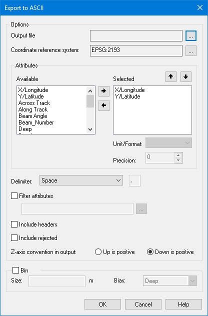
Export Coverage to ASCII uses the Export to ASCII dialog box.
Values entered in this dialog box that are not dependant on the current dataset will be remembered for future use. |
Option | Description |
|---|---|
Output file | The name and location for the resulting ASCII file. |
Coordinate reference system | The coordinate reference system (CRS) to use for the export. The CRS of the input coverage is selected by default. 1. Click the browse (...) button to launch the Select Coordinate Reference System dialog box. See Coordinate Reference System Selection 107for information on using this tool. 2. Select a CRS and click OK. |
Available | All attributes in the input coverage that are available for export. Attributes can be added to the Selected list multiple times, allowing the values to be exported with different units and precision. 1. Select the desired attribute in the Available list. 2. Click the right-arrow button to move it to the Selected list. |
Selected | The attributes of the input coverage that have been selected to be included in the export. The order of the attributes in this list controls the order of the attributes in the output file. The order can be changed as needed using the up-arrow and down-arrow buttons when an attribute is selected in the list. Attributes can also be removed from the Selected list using the left‑arrow button. 1. Select an attribute in the Selected list. 2. Click the up-arrow or down-arrow button to change the order of the attributes. |
Unit/Format | The horizontal position units or format to use for the values of the active attribute. The following units are supported: ac, cable, ch, cm, cm2, day, dB, deg, deg/s, fm, fm2, ft, ft/s, ft2, ft3, ha, hour, in, inm, km, km/h, km2, kn, m, m/s, m2, m3, mi, mi/h, mi2, min, mm, mm2, nm, nm2, rad, rad/s, sec, usac, usfm, usfm2, usft, usft/s, usft2, usft3, usmi, usmi/h, usmi2, usnm, usyd, usyd2, usyd3, week, yd, yd2, yd3, DD, D-M, D-M-S, DMS The units available differ depending on the data type of the selected attribute. • For band values, all supported distance units are available. • For position values, the available options depend on the selected CRS: • For a projected CRS, the list includes all available units and formats and defaults to metres. • For a geographic CRS, the list includes angular units only and defaults to DMS (N/S/E/W). The selected unit for position values also controls the column headings that will be populated in the output file, if the Include headers option is enabled. • For distance units, headings will be X and Y • For angular units, headings will be Latitude and Longitude This field is disabled if the selected attribute contains unitless values. 1. Select the attribute in the Selected list. 2. Select a unit/format from the drop-down list. |
Precision | Assign a precision value to each attribute being exported. The precision determines the number of decimal places in the exported values. Up to nine decimal places are allowed. 1. Select the attribute in the Selected list. 2. Select or type a precision value in the field. |
Delimiter | The character used to separate attribute values in the ASCII file. This character makes it easier to distinguish the exported values for each attribute. A space, comma, or tab are provided as options, but any single alphanumeric character can be used. |
Filter attributes | On: Filter out data you do not want included in the export, for example, interpolated nodes. Filtering is performed according to attribute values using an equation built in the Filter Attributes dialog box, which is launched from the Filter attributes browse (...) button. See Filter Attributes for information on using the Filter Attributes dialog box. Off: All data is exported for the selected attributes. |
Include headers | On: The first row of the ASCII file is populated with column headers for the selected attributes. Off: The first row of the ASCII file is populated with attribute values. |
Include rejected | On: Include rejected soundings in the export. By default, soundings flagged as rejected are not included to ensure that a clean surface can be created from the exported data. Off: Rejected soundings are excluded from the export. |
Z-axis convention in output | Define the Z-axis convention of the data in the exported file. By default, the export will use the direction defined in the Z-axis Convention option in the Coverages category of Tools > Options, but this setting will override that setting. If the exported Z values are required to be Z-axis positive up, select Up is positive. If the exported Z values are required to be Z-axis positive down, select Down is positive. |
Bin | Nodes in the selected coverage can be exported as binned (each in its original position in the grid cell). Click the check box to enable the binning options. |
Size | If full resolution is not required for the data, a lower resolution size can be specified. |
Bias | Export the data with either a shoal or deep bias. |
The Bin options are only available if exporting with the BASE Editor licensed module. |
Procedure
1. In the Layers window, select the layer containing the data to be exported.
2. Select the Export Coverage to ASCII command.
The Export to ASCII dialog box is displayed.
3. Click the Output file Browse button (...) and specify a name and location for the ASCII file.
4. Click the Coordinate reference system browse button (...) to launch the Select Coordinate Reference System dialog box and select a coordinate system. See Coordinate Reference System Selection 107for information on using this tool.
5. Select the attributes to be included in the output and define their order in the list.
If a colour band is selected for export, the colour values will always export as four separate columns and in the order red, green, blue, alpha. |
6. Select the Units to use for each attribute in the Selected list.
7. Specify the Attribute precision for each attribute in the Selected list.
8. Select the Delimiter to be used in the output file.
9. Select the Z-axis convention to use for the exported elevation values.
10. Complete any other optional settings as needed.
11. Click OK to perform the export.
The source data is exported to a new ASCII text file.
If the export includes nodes with no known value, they will be assigned a value like -99999.0, depending on the band type. This allows no-data nodes to be easily identified in the output. |
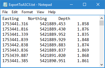
The resulting text file should look something like the image below.