Menu | Tools > Coverages > TIN > Digitize Breakline |
Tool |
|
Pop-up | TIN Editor > Digitize Feature > Breakline (Layers window) |
Menu | Tools > Coverages > TIN > Digitize Breakline |
Tool |
|
Pop-up | TIN Editor > Digitize Feature > Breakline (Layers window) |
The Breakline command allows you to create a new breakline for the TIN.
A breakline object (brklne) is used to insert known elevations and depths into the TIN. Breakline objects can be either line or area objects. Once a breakline object is applied to the TIN, the model includes the vertices of the breakline and the value of their depth attribute.
By default, the line is digitized using the point-to-point method, however, there are numerous line-digitizing methods available for creating the breakline.
Procedure
1. Select the TIN Editor layer in the Layers window.
2. Click the check box to turn on the TIN Editor layer.
3. Select the Breakline command.
The Tool Depth dialog box is displayed.
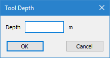
4. Enter the depth for the breakline in the Depth field.
5. Click OK.
The cursor changes to digitizing mode.
6. Click to place the first node of the line.
7. Continue adding vertices as needed.
8. When the line is complete, use one of the following methods to end digitizing:
• Right-click and select End Line or press the <End> key to create the line as is.
• Right-click and select Close Line or press the <Home> key to create a closed shape using the first and last nodes of the line.
The breakline is created, however, it is not applied to the TIN.
9. Select the Update TIN command to apply the new breakline to the TIN and save the changes to the TIN Editor layer.
Menu | Tools > Coverages > TIN > Update TIN |
Tool |
|
Pop-up | Update TIN (Display window) |
10. Refresh the Display window.
The TIN is updated based on the breakline.

