Menu | Tools > SIPS Mosaics > New > select engine |
Tool |
|
Menu | Tools > SIPS Mosaics > New > select engine |
Tool |
|
Create a mosaic using one of three HIPS processing engines:
• SIPS Backscatter: processes multibeam backscatter (both beam-averaged and the higher resolution time-series returns), employing such corrections for backscatter intensity as TVG, transmit and receiver gain, and beam pattern correction
• SIPS Side Scan: processes side scan using imagery corrections such as TVG, gain and despeckle as well as beam pattern correction to create mosaics from selected track lines.
• Geocoder: processes multibeam backscatter, both beam-averaged and the higher resolution time-series returns, as well as side scan sonar data.
Interface
New mosaics are created using the New SIPS Mosaic dialog box
.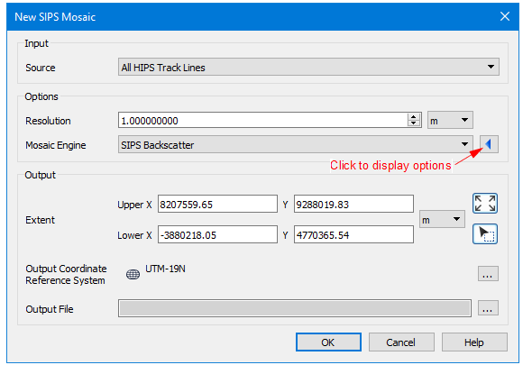
The New SIPS Mosaic dialog box is structured to hide fields that are optional for the creation of a mosaic. These include options such as imagery correction, filtering, weighting etc, that are displayed based on the type of mosaic engine selected. These can be displayed by clicking the blue arrow the right of the Mosaic Engine field. Options vary with the choice of engine.
An example of an expanded dialog box is displayed below.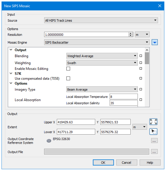
Hover your cursor over any field name to see a brief description of its function.
Procedure
1. Zoom/pan to display the extents of the data that you want included in the mosaic.
2. [Optional] Select one or more track lines. If no track lines are selected, the mosaic will be created using on all open track lines.
3. Select a New SIPS Mosaic command.
The New Sips Mosaic dialog box is displayed.
4. Set the Input Source for the mosaic.
• If lines were selected before opening the dialog box, the Source field is set to “Selected Track Lines”, and only those lines will be included in the mosaic.
• If no lines were selected, the field displays “All Track Lines” and the mosaic will be created from all open lines.
• The Source setting can be changed to All Track Lines.
5. Set a Resolution and units for the mosaic.
• Use the spin box arrows to select a value for the resolution of the mosaic image, or type a numerical value.
• [Optional] Change the units of resolution from the list to the right of the Resolution field.
A resolution must be set for mosaics from side scan or backscatter data.
6. Select a Mosaic Engine.
7. Expand the options fields for the selected mosaic engine and set options for the type of engine.
See SIPS Mosaic Options for details on settings.
8. Set Extent for the mosaic.
9. Click Browse in the Output Coordinate Reference System field to set the horizontal coordinate reference system for the output mosaic.
An output CRS must be set for all mosaics.
10. Click Browse for the Output File and set name and path for the output mosaic.
There must be a defined name or the mosaic will not be created.
11. Click OK to create the mosaic.
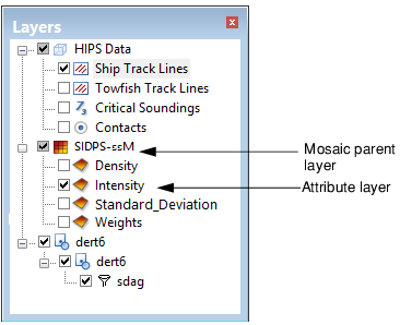
The new mosaic is displayed in the Display window and is listed in the Layers window.