Menu | Process > Beam Pattern > Create > Backscatter |
Tool |
|
Menu | Process > Beam Pattern > Create > Backscatter |
Tool |
|
Beam pattern files can be created from SIPS backscatter data from a line or lines selected in the Display window. The new beam pattern file will have a *.bbp extension.
Interface
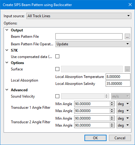
Beam pattern creation using SIPS Backscatter uses the following dialog box:
.
Option | Description |
Input Source | • To create the beam pattern file from the selected line or lines, set the Source field to Selection. • To create the beam pattern file from all open lines, select the All Track Lines option. |
Output | Name and destination of the beam pattern file. |
Beam Pattern File | 1. Click Browse in the field and enter a name for the beam pattern file. A Beam Pattern file must be selected. 2. Click Save. |
Beam Pattern File Operation | If a beam pattern file already exists for the selected data, this field displays “Update”, and the existing beam pattern will be applied. 1. [Optional]] Select “Overwrite” to replace the existing file with a new beam pattern. |
S7K | |
Use compensated data (7058) | 1. Select this option to use compensated intensity data instead of raw data. If no compensated data is found on a line, the line will not be used for the beam pattern. |
Options | |
Surface | The path to the surface used to compute the local bottom slope used in the calculations of real incidence angle and ensonified area. The default elevation band will be used. If surface is not set the processed bathymetry will be used by default. 1. Select the check box to enable the Browse button. 2. Browse to and select a surface. |
Local Absorption | Correction for transmission loss using temperature and salinity values. 1. Set temperature value in degrees. Default value is 8.00 1. Set salinity value as parts per thousand. Default value is 35 parts per thousand. |
Advanced | |
Sound Velocity | Enter the velocity value applied during slant range correction. (This will over-ride the use of Surface Sound Speed.) When SSS is not available a value of 1500 m/s is used. 1. Click the check box and enter a value. |
Transducer1 (Angle Filter) | This field displays the angle from nadir values set for Transducer1 in Port and Starboard fields. 1. Set values in degrees of the angle to port from nadir. 2. Set values in degrees of the angle to starboard from nadir. |
Transducer2 (Angle Filter) | This field displays the angle from nadir set for Transducer2 (in a dual system) in Port and Starboard fields. 1. Set values in degrees of the angle to port from nadir. 2. Set values in degrees of the angle to starboard from nadir. |
The new file will have a *.bbp extension.
You can view a loaded beam pattern in the Signal Display window, where it will appear as a yellow line. See Open Signal Display Window.
Menu | Process > Beam Pattern > Create > Side Scan |
Tool |
|
Beam pattern files can be created from lines selected in the Display window, or from all open track lines.
Beam pattern files can also be created from a range of pings selected in the waterfall view in Side Scan Editor.
Interface
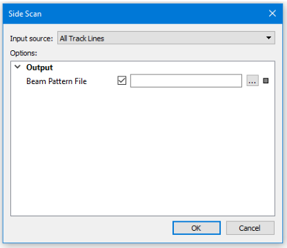
Beam pattern creation using SIPS Side Scan uses the following dialog box:
.
Option | Description |
Input Source | The source of the data: • To create the beam pattern file from the selection, set the Source field to Selection. • To create the beam pattern file from all open lines, select the All Track Lines option in the Source field. |
Beam Pattern File | Name and destination folder for the beam pattern file. 1. Click Browse in the File Name field and enter a name for the beam pattern file. 2. Click Save. |
1. Select the input source.
2. Set the name and designation of the beam pattern file.
3. Click OK to create the side scan beam pattern file.
The new file will have a *.bp extension.
You can view a loaded beam pattern in the Signal Display window, where it will appear as a yellow line. See Open Signal Display Window.

