Menu | Tools > Coverages > Bounding Polygon > Digitize |
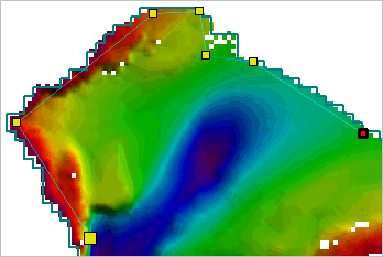
Raster surfaces, point clouds and variable resolution (VR) surfaces created or updated in CSAR format automatically include a bounding polygon that encompasses the entire extents of a coverage. This polygon is not included in the display by default. If you want to view or edit the polygon, you must first add it to the display using the Add Bounding Polygon Layer command. See Add Bounding Polygon Layer for more information.
The level of detail used to create the polygon is controlled by the Bounding Polygon Level option in the Coverage category of Tools > Options. This setting is used anytime a coverage is created or updated, which triggers the creation or update of a bounding polygon. The default setting is Medium, but can be changed if desired.
The bounding polygon can be recreated if the automatically generated polygon is not acceptable. When redigitizing an entire polygon, the existing polygon will need to be removed manually. Alternatively, additional polygons can be added if you have a disjointed surface and require multiple polygons.
By default, a bounding polygon is digitized using the point‑to‑point method. You are not limited to this method, however, there are several digitizing methods available. The method can be changed at any time without damaging the polygon. For more information on the digitizing methods, see Digitize.
The Grab tool is a useful digitizing tool when creating polygons. It allows you to select a pre-existing polygon feature on another layer and it then creates a copy of the feature on the Bounding Polygon layer. See Grab for more information.
Related commands:
• Add Bounding Polygon Layer
• Rebuild Bounding Polygon Automatically
• Exporting a Bounding Polygon
Procedure
1. Select the Bounding Polygon layer for the relevant coverage.
2. Select the Digitize Bounding Polygon command.
Digitizing mode is enabled. Note the change in the cursor’s appearance.
3. [Optional] Right-click and select Edit Line to choose an alternate digitizing method.
4. Click the Display window to add vertices until the polygon has the appropriate shape and size.
If necessary, the <Backspace> key can be used to remove the last vertex added. |
5. Use on of the following methods to turn off Digitizing mode and complete the bounding polygon:
• Select the Digitize New Boundary Polygon command again.
• Right-click in the Display window and, from the pop-up menu, select Edit Line > Close Area.
• Press the <End> key.
The newly digitized boundary is added to the display.