Menu | File > New |
Tool |
|
A process model file contains all the required configurations for each process added to the file. Tools should be arranged in the workflow order in which they will be processed, and connected to indicate that the output of one tool is the input of the next.
Process tools can have a number of inputs and an output connection port. Conditional tools, such as “Exists” or “Branch”, which use a logic function, and other model tools such as can have more than one output.
To create a new process model file:
1. Click New or select New from the menu to open an empty model window.
Menu | File > New |
Tool |
|
2. Add a tool to the model window, either by:
clicking on a process in the Tools window, and dragging it to the window, or
by double-clicking the tool name in the Tools list.
A tool being dropped into or moved in the model view always snaps to the underlying grid. When the tool is displayed in the model view, the options for the selected tool are displayed in the Properties window.
A blue outline around a tool indicates it is selected.
3. Set the properties for the tool. See Tool and Properties Status Indicators.
4. Add parameters and values, by selection from the right-click menu on the tool. See Parameter and Value.
5. Add further tools and connect them in the sequence in which they will be applied.
Connect tools
To connect tools:
6. Click on a connector on one tool, for example an output, and drag a line to connect it to the input of the second tool.
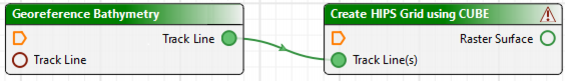
7. Release the line and it will automatically attach to the second process.
Once all the required tools have been added and configured:
8. Click Save or select the Save command from the menu.
Menu | File > Save |
Tool |
|
9. In the Save As dialog box, navigate to the location where you want the file saved.
10. Type a name for the process model file.
11. Click Save to save the file to your desired location.

