Menu | Tools > Surfaces > New > Regular Gridded |
Tool |
|
Menu | Tools > Surfaces > New > Regular Gridded |
Tool |
|
Regular gridded surfaces can be created from a specific track line or lines, from a defined area or from the full extents of the data.
You do not need to select a data line or lines before starting to create a surface. If you do select a line, there is an option to use only the selected lines in the surface. If this option is selected, the extents settings will only apply to those selected lines.
Surface creation is not interrupted if it encounters bad data. The process will skip the part of the line containing bad data and continue creating the surface with the next line. Once the surface is complete you can decide whether or not to remove the partial line.
All track lines must be merged before a surface can be created. |
Surfaces are created using one of these methods:
• Shoalest Depth True Position
• CUBE
See Gridded Surfaces for descriptions of each type of surface.
Interface
Gridded surfaces are created using the New Regular Gridded Surface dialog box.
The New Regular Gridded Surface dialog box is structured to hide fields that are optional for the creation of a surface. These options can be displayed by clicking the blue arrows at the right of the dialog box. Options vary with the choice of gridding method.
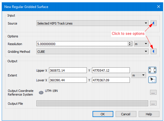
An example of an expanded dialog box is displayed below.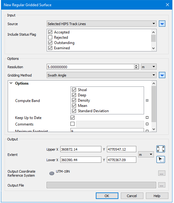
Hover your cursor over any field name to see a brief description of its function.
Option | Description |
Input | |
Source | If one or more track lines were selected before the surface creation process was started, the Selected Track Lines option is selected. Otherwise All Track Lines is set. |
Include Status Flag | By default, data with Accepted, Examined or Outstanding status are set to be included in the surface. Suppressed or Rejected data can be included in the surface by selecting the check box. 1. Select the check boxes for the flagged data to include in the surface. |
Options | |
Resolution | The Resolution value sets the distance(s) between surface nodes. The same single resolution value for the entire surface is set based on a range of depths to include in the surface by using the Depth Filter option. Resolution value uses the units set in Tools > Options > Display > Units > Ground Units. |
Gridding Method | Depending on the method selected certain options are made available. See Gridding Methods. |
Output | |
Extent | The extents of the new surface are based on either the data currently visible in the Display window, or within a drawn area. |
1. Zoom in on the area you want to include so that it fills the Display window. 2. Click the Current Display Extent button. The Upper and Lower X and Y fields display the dimensions of the area in the display, using ground units as set in Tools > Options > Display > Units. | |
1. Click the Bounding Box button. The cursor in the Display window is shown as a cross-hair + . 2. Press and hold the mouse button, and drag the cursor across the area to include in the surface. 3. Release the mouse A rectangular box is drawn across the area and its coordinates are displayed in the extents fields. You cannot move the bounding box, but you can re-draw it as long as the New surface dialog box is still open. | |
Set extents by entering coordinates: Enter the Upper X and Lower X and Upper Y and Lower Y coordinates. • by clicking in one of the appropriate fie Ids and typing the coordinate data, or • by using the arrow keys to toggle the values in the entry fields. | |
Output Coordinate Reference System | 1. Click Browse to open the Select Coordinate Reference System dialog box and set the desired CRS. |
Output File | 1. Click Browse. 2. Select a destination folder for the surface file. 3. Type a name for the surface file and 4. Click Save |
Procedure
1. Select the Tools > Surfaces > New > Regular Gridded command.
2. Select the source data from the list.
3. Select status flags for data to be included in the surface.
4. Enter a resolution value.
5. Select a gridding method.
6. Set the extent of the surface.
7. Set an Output Coordinate reference system.
8. Name the surface click Save.
9. Click OK to create the surface.

 Set extents using current display:
 Set extents by drawing a bounding box: