Menu | View > 3D View |
Tool |
|
Redraw an open 2D view as a 3D scene.
You can fly through a 3D scene to view points, areas and other features, and you can record your fly-throughs for playback and review outside of Easy View. See the next exercise, Fly Through a Scene, for more detail.
The following files should be open:
• Surface1m_Contour
• Surface1m_interp
For Surface1m_interp, the Colour Map property for the layer should be Rainbow [Map].
Refer back to Create Display Layers if these files are not open or the property not set.
Menu | View > 3D View |
Tool |
|
1. Open a raster image.
2. Select the 3D View command.
The 3D View opens in the Display window. 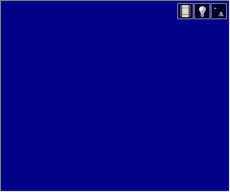
The 3D view is in a separate Display window. If you look at the Windows menu, you will see two open windows. |
Tools > Options provides a set of 3D options under the Display category that can be used to adjust the display of the window and turn on/off tools and components in the 3D View, such as the Controller panel and Colour Legend. For example, the View Style option determines whether the 3D View window will automatically use the full Display window area or be tiled along side the 2D Display window. 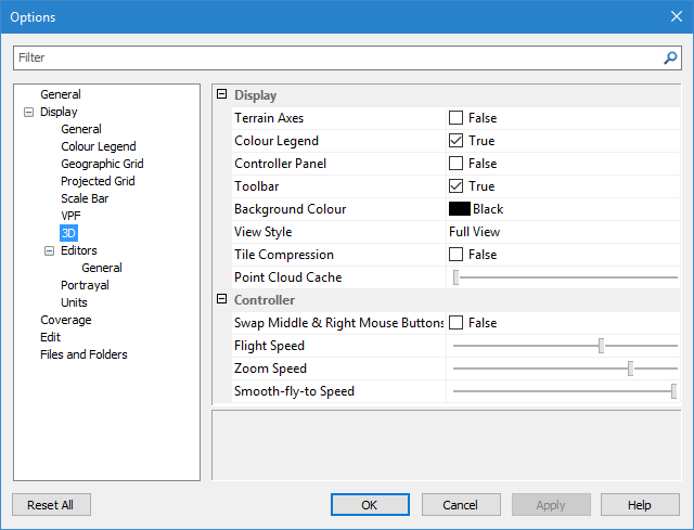
Before working with data in this view, you may want to set these options.
When the 3D View is enabled and selected in the display, the Layers window is used to control the layers that are turned on or off in the 3D View. If the normal 2D Display window is selected, the Layers window will return to its normal behaviour for the 2D view.
3. In the Layers window, turn on the Surface1m_interp layer.
The surface is displayed in 3D.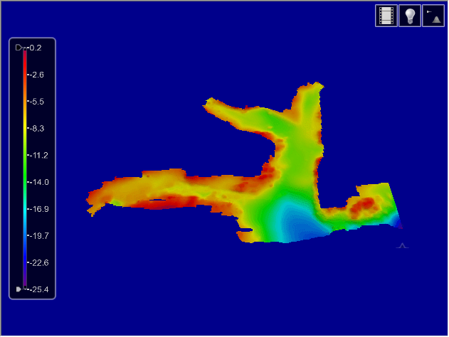
The tools provided in the 3D window toolbar are:
Tool | Control | Description |
| Recording | Displays a control panel for creating and playing fly-through recordings. This is described in more detail in Fly Through a Scene. |
| Vertical Exaggeration | Displays a control panel for setting vertical exaggeration, |
| Lighting | Displays a control panel which adjusts the azimuth and elevation of the main light source. |
In the 3D view, you can drape raster images over coverage data.
4. Turn on the raster image layer.
5. Select the Surface1m_interp layer in the Layers window to make it the active layer.
6. Under the Colour category in the Properties window, expand the drop-down list for the Drape property and select the raster image.
The image is draped over the coverage in the 3D View.
Vertical Exaggeration
Next, use the vertical exaggeration control to change appearance of the terrain.
Tool |
|
1. Click the Vertical Exaggeration button to display the slider control. 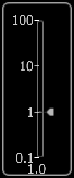
The Vertical Exaggeration slider is displayed.
2. Drag the arrow to 10.
3. Release the mouse button.
The scene is redrawn.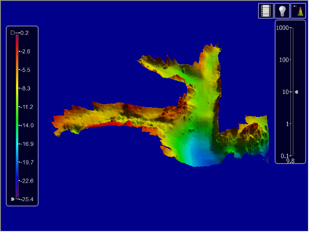
4. Click the Vertical Exaggeration button again to close the slider.
Note that the height or depth of the terrain has been exaggerated to make features more obvious.
If you zoom in, you can see that the contours have also been exaggerated.
Lighting
Now adjust the lighting:
1. Click the Lighting button to display the lighting control.
Tool |
|
The Lighting control is displayed.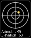
The yellow dot within the sundial represents the light source.
The current azimuth and elevation of the light source is displayed at the bottom of the control.
2. Click on the light source and drag it within the sundial.
Note the effect on the surface.
3. Click the Lighting button again to close the control.
Colour Legend
If the colour legend is turned on in Options and the displayed layer is selected in the Layers window, the colour legend for the data is displayed in the 3D View. The maximum and minimum colours for the colour range can be changed using the two slider controls in the legend.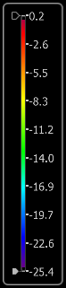
1. Drag the controls up or down.
Note the effect on the surface.
2. Drag one control so that it passes the other.
The colour range is reversed.


