Menu | Tools > Coverages > Thin Points |
Pop-up | coverage layer > Tools > Thin Points (Layers window) |
The Thin Points command is used to create a new CSAR point cloud containing a subset of the points from an existing coverage. Thinning can be performed on raster surfaces, point clouds or variable resolution surfaces.
You may wish to thin points if:
• you only need a sample of the data,
• the current task does not require the density level present, or
• the file size is slowing down data transfers and processing times.
There are three possible methods that can be used to thin points:
• Apply Bias: This method sorts points according to their values and then suppresses the points in the list according to the user-specified radius and range values. When sorting points, designated soundings are considered before all other points. Suppression begins with the value at the top of the list, which can be either the least or the greatest value in the band, depending on the z-axis convention. The input band for this method can be any available numeric attribute, such as elevation, uncertainty or temperature. This method can be used as a replacement for Sounding Selection as Thin Points is capable of handling larger datasets.
• Minimum Distance: This method deletes points that are closer than a user-specified distance until all remaining points are separated by at least the minimum distance value. The starting point is selected randomly based on a deterministic algorithm, so running the process on the same dataset multiple times with the same settings will produce the same output each time.
• Random: This method randomly removes points until a user‑specified percentage of data has been removed. The retained points are selected using a deterministic algorithm, meaning that points will be randomly selected, but running the process on the same dataset multiple times with the same settings will produce the same output each time.
Because thinning is performed randomly in the Minimum Distance and Random methods, only the Apply Bias method can be used to produce a sounding selection that is suitable for use in a chart production workflow.
Interface
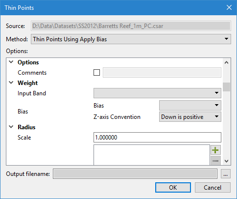
The Thin Points command uses the following dialog box.
Option | Description | |
Common Options | ||
Source | The input data for the process. The Source is defined by the surface that was selected at the time the command was initiated. This field cannot be changed. | |
Format | The thinning method to apply to the source dataset. The options in the dialog box will differ based on the option selected. | |
Common | Include Band | The bands from the source dataset to include in the output point cloud. Values from all selected attributes will be retained in the output points. 1. Click the check box of each band to include. |
Options | Comments | General comments about the data to be included in the metadata of the output point cloud. 1. Click the check box to enable the text field. 2. Enter the relevant text into the field. |
Output filename | The name and location for the output file. | |
Thin Points Using Apply Bias Options | ||
Weight | Input Band | The band of the source dataset containing the values to be thinned. |
Bias | Define whether the maximum value or the minimum value of the selected attribute should be retained during thinning. The z-axis convention of the input data must be identified in order for the application to determine whether values are increasing or decreasing based on their direction. If the application is using the positive-down z-axis convention, a minimum bias would be used to retain the shoalest values. In a positive-up application, a maximum bias should be used to retain the shoalest values | |
Radius | Scale | Enter a value to apply a scale to the minimum distance value. If using distance on the ground, keep the default scale of 1:1. If using a distance at map scale, you must enter a scale value, such as 1:1000. |
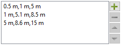
Minimum Distance | The minimum distance between points in the output point cloud. Points from the input that are closer than the minimum distance will be removed during thinning. The distance can be specified as either a single radius value or a set of intervals and radii. • For a single radius value, the application will ensure that no two points are closer than the minimum distance. This value is entered as either a distance on the ground or a distance at map scale, depending on the Scale value, and is applied to the entire band. • Sets of intervals allow a different radius to be used at different value ranges. This is beneficial if data is more dense at lower values, requiring a smaller radius to apply more thinning, while the data is less dense at higher values, requiring a larger radius to perform less thinning. To specify a minimum distance interval, you must provide the radius distance and the minimum and maximum values of the range for which to use that radius. If there is a gap between the range values specified, the application will use linear interpolation to select radii for those values. You must also identify the z-axis convention of the input data in order for the application to know the direction in which to apply the minimum and maximum values. 1. Click the Add button to launch the Add Value dialog box.
2. Enter a Radius value and select the unit of measure. 3. If specifying multiple intervals, click the check boxes to enable the Minimum and Maximum options. 4. Enter the Minimum and Maximum values to include in the range of values and select the unit of measure for the interval range. 5. Select the Z-axis Convention of the input data. 6. Click OK. 7. Repeat for each thinning interval you want to use. | |
Minimum Distance (cont.) | The intervals and radii are listed in the Minimum Distance box. The other buttons beside the box can be used to reorder the intervals or remove an interval.
| |
Apply Designated | Select this option to include designated soundings in the output and define how they should be handled during thinning. • Multiple Designated: This setting defines how to handle designated soundings that are closer to each other than the specified minimum distance. You can opt to include all designated soundings or thin them, according to the specified settings and include the remaining designated soundings. • Bias Relevance: This setting defines how to handle designated soundings that are closer to normal points than the specified minimum distance. You can opt to thin points according to the specified settings and include the designated soundings as well, or override the specified settings and include only the designated soundings within the specified radius, thinning all other points in the same radius as the designated sounding. 1. Click the check box to enable the Apply Designated fields. 2. Select an option from each drop-down list. | |
Thin Points Using Minimum Distance Options | ||
Radius | Minimum Distance | The minimum distance between points in the output point cloud. Points from the input that are closer than the minimum distance will be filtered. 1. Specify a distance value either using the Up and Down Arrow buttons or by typing a value in the field. 2. Select a unit of measure from the drop-down list. |
Scale | Enter a value to apply a scale to the minimum distance value. | |
Thin Points Using Random Options | ||
Weight | Percentage | The percentage of data to be removed. |
Example: Apply Bias
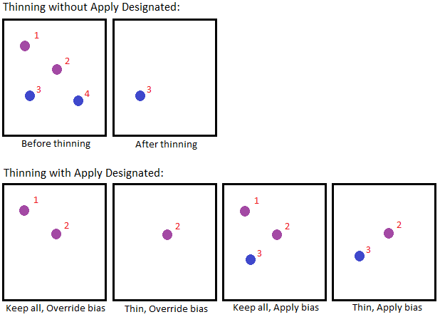
There are several possible outcomes when thinning with the Apply Bias method, depending on the selected settings. The image below depicts the possible outcomes for 4 points in a dataset using a Bias of Minimum when the active z-axis convention is "down is positive", with and without applying designated soundings. The details of the points are:
• Point 1: Designated with a depth of 6m
• Point 2: Designated with a depth of 5m
• Point 3: Non-designated with a depth of 4.5m
• Point 4: Non-designated with a depth of 7m
Procedure
1. Select the coverage to be thinned in the Layers window.
2. Select the Thin Points command.
The Thin Points dialog box is displayed.
3. Select the thinning Format to apply.
4. Select the bands to include in the output.
5. Define any necessary settings for the selected thinning format.
6. Specify a name and location for the output file.
7. Click OK.
A new point cloud is created in the specified location containing only points that met the thinning criteria.