There are a number of modifications that can be applied to an alignment after it has been created.
• The alignment points can be manually repositioned in the Display window.
• The direction of the alignment can be reversed.
• The alignment properties can be modified in the Model Feature window.
An end point of a curved alignment that is shared with another curved alignment cannot be modified as there is no way to do so and preserve both arcs. |
Related commands:
• New Alignment from Existing Alignments
• New Alignment From Superselection/ Selection
Procedure: Change Point Locations
1. In the Layers window, select the Alignments layer.
2. Superselect the desired alignment in the Display window.
3. Click to select the desired point in the alignment, keeping the mouse button pressed.
4. Drag the point to a different position.
5. Release the mouse button.
The alignment is updated. To save your changes select the Save command.
Procedure: Change Direction of Alignment
The direction of an alignment can be reversed using the Reverse Direction command. Reversing a compound alignment will automatically reverse the full alignment as well as the individual straight and curved alignments it contains. Note that an alignment cannot be reversed if it is being used to define other features, such as points, stations, or profiles. If part of a compound alignment is being used by another feature, its direction cannot be reversed; compound alignments must be reversed as a whole.
1. In the Model window, select the alignment feature you want to modify, or superselect the alignment in the Display window.
2. Select the Reverse Direction command.
Menu | Edit > Lines > Reverse Direction |
The direction of the alignment is changed.
Procedure: Change Alignment Properties
1. In the Model window, select the alignment feature you want to modify, or superselect the alignment in the Display window.
The Model Feature window is populated with information for the selected alignment.
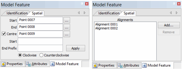
2. In the Model Feature window, select the Spatial tab.
The Spatial tab of the Model Feature window is displayed.
• If you selected a straight alignment, the Start and End fields are populated with the start and end points of the alignment. The browse buttons (...) can be used to change these points.
• If you selected a curved alignment, the Centre field is enabled and populated. The browse button (...) can be used to change this point. The Start, End Prefix, and Clockwise/Counterclockwise options are also enabled. These fields are only enabled if the Centre field is populated (i.e., when the Centre checkbox is checked). With these fields, new prefix values can be entered and the direction of the alignment can be changed.
The spatial properties of a straight or curved alignment cannot be modified if they are part of a compound alignment or another feature. |
• If you selected a compond alignment, a list of the alignments used to create the alignment is displayed. The Add and Remove buttons can be used to change the alignments that make up the compound alignment.
The Remove button is disabled (greyed out) if the selected alignment is the only remaining alignment in the compound alignment. |
3. Make any necessary changes for the selected alignment.
4. For straight and curved alignments, click Apply to confirm the changes.
The alignment is updated with any changes. To save your changes, select the Save command.