Menu | Tools > Engineering Analysis > Volumes > Hyperbolic/Rectangular/Triangular |
Tool |
|
Depending on the type of data selected, there are three types of volume computations that can be performed:
• Hyperbolic: A hyperbolic cell is created from the centres of every four adjacent grid cells. The depths from the grid cells are used as the depths of the corners of the hyperbolic cell. For this calculation, the surface is modelled as a collection of hyperbolic paraboloid sections, with a hyperbolic paraboloid created to smoothly pass through the points of each hyperbolic cell. This gives a smooth approximation of the surface.
• Rectangular: A single depth value from each cell in the surface is used to calculate volume. For this calculation, the surface is modelled as a collection of disjointed rectangular prisms.
• Triangular: The true position for the depths of the cells in a TIN are used to calculate the volume of a surface. For this calculation, the surface is modelled as a collection of interconnected small planes. You must have a TIN created and selected to use this method. For TINs created from raster surfaces gridded to a plane, volumes are calculated against the plane, not against any other model. If needed, the plane can be shifted using the Infinite plane Offset option.
To calculate volumes:
1. If using a reference model as the reference plane, ensure the reference model is open.
2. Open the surface for which you want to calculate volume.
Menu | Tools > Engineering Analysis > Volumes > Hyperbolic/Rectangular/Triangular |
Tool |
|
3. Select a layer in the surface containing elevation values.
4. Select the Volumes command appropriate to your data.
The Hyperbolic/Rectangular/Triangular Volumes dialog box is displayed.
The title of this dialog box will differ based on the command selected. Also, the "Depth" field is displayed when the Z-axis convention is positive down; "Height" will be displayed when the convention is positive up. |
You can choose to use the surfaces in one or more reference model templates or an infinite horizontal plane as the reference for volume calculation.
When using reference model surfaces, their limited planes will be used to calculate the volumes in defined areas, and their Allowance Below attributes will be used when computing an allowance. When using an infinite horizontal plane, the volume will be calculated for the entire surface at once and you must specify the reference depth of the plane and the Allowance below the plane to be used.
To use a reference model surface, continue with the next step. Otherwise, to use an infinite horizontal plane, go to step 8.
5. For hyperbolic or triangular volumes, select the Reference model surfaces option. For rectangular volumes, select the Horizontal reference model surfaces option.
6. In the list on the left, select the reference model template that contains the surface to be used.
The reference model surfaces available in the selected template will be listed in the box on the right.
7. Select a surface from the list on the right and go to step 11.
8. Select the Infinite horizontal plane option.
You need to specify the Depth/Height and the Allowance for the plane. These values will be entered in the unit of measure currently selected in the Display Units options. Depth/Height is the depth/height of the plane being used as a reference. Allowance is the distance below the plane that is of interest.
9. Enter a Depth/Height value.
10. Enter an Allowance value.
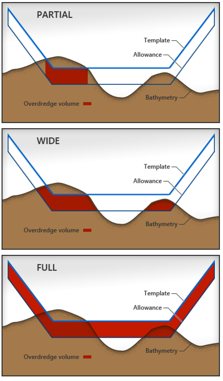
The Allowance Algorithm controls which method is used to calculate allowance volumes. You can opt not to apply an algorithm, or you can choose from one of the three algorithms provided:
• Partial Bottom: Calculates allowance volume only for the area of the model which has excess volume at the model depth.
• Wide Bottom: Calculates the allowance volume for the area of the model that has excess volume at the allowance depth/height. The allowance volume reflects the actual volume of material between the allowance depth/height and the model depth.
• Full Bottom: Calculates allowance volume for the entire model area regardless of the location of the material to remove.
An example of each option is shown below.
11. Select an option from the Algorithm list.
The results of the calculation will be saved to an XML file that can be reopened at a later date. By default, the file will be saved to the Windows Temp folder the first time the command is run.
C:\Users\<username>\AppData\Local\Temp
If you choose to save to a different directory, that directory will be selected by default the next time the command is run.
12. Click the Output filename Browse (...) button to define a name and location for the results file.
13. Click OK to perform the calculation.
A progress bar will be displayed to track the progress of the calculation. As each selected reference model surface is calculated, the results will be displayed in the Output window as raw data, meaning values have not been rounded or converted to the unit of measure being used in the application. If volume cannot be calculated for any reason, the name of the problematic surface will be output with an error message as the last entry in the Output window and the operation will stop.
When all calculations have finished, the results will be displayed in the following dialog box and saved to the specified XML file.
See Open Volume Results for more information on the results dialog box.
 ,
,  ,
, 