Menu | Tools > Surfaces > Difference |
Tool |
|
Menu | Tools > Surfaces > Difference |
Tool |
|
Create a coverage showing the differences in attribute values between raster surfaces (local and/or database), Point Clouds, Reference Models, and/or TINs. Difference can also be calculated between different bands in a single coverage.
A license for the Engineering Analysis module is required to use reference models in the difference process. |
To use this tool, you must select two files (Input A and Input B) that cover part or all of the same area, or a single file containing multiple bands for a comparison. These files can be any combination of the supported surface types (a BASE Surface and a Reference Model, a BASE Surface and a Point Cloud, and so on).
Input B will be subtracted from Input A to calculate the difference. A new coverage is generated for the difference; the new coverage will be the same type as Input A. For example, if Input A is a point cloud, the new coverage will be a point cloud.
The resolution of the new coverage will be the same as the resolution of the coverage selected for Input A. |
If the two coverages do not share the same vertical coordinate system, the Vertical Coordinate System property for the resulting system is controlled by that of Input A. If this property has not been defined for Input A, the resulting surface also will have no vertical coordinate system defined.
Interface
The Difference Surface command uses this dialog box:
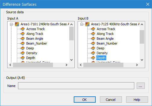
Option | Description |
Input A | The coverage and attribute band selected as input 1 for the comparison. |
Input B | The coverage and attribute band selected as input 2 for the comparison. |
Output (A-B) | The name and location for the resulting difference surface. |
Procedure
1. Select the Difference Surface command.
2. Select an attribute band from Input A and Input B for the coverages to be compared.
Point Clouds are not included in the Input B list because the second coverage must be a surface. Surfaces have values defined over an area, not at a series of precise, discrete X,Y locations. |
3. Specify a name and location for the Output surface.
4. Click OK.
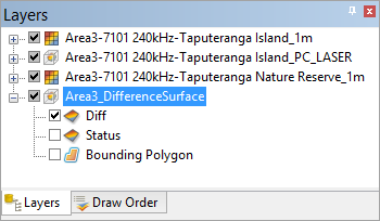
The difference surface is created and added to the Layers window.
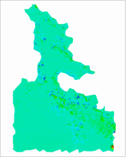
The colours of the difference surface represent the range of discrepancies between the two input sources. The dark areas of the surface represent greater depth differences than the light areas. If the contrast is not clear, the colour map settings can be changed using the Colour File property in the Properties window. See Colour Map Editor for more information.
Example:
Surface Difference is useful for comparing changes to an area. A surveyed area can change considerably over time due to the redistribution of sediment with the currents. This redistribution can cause changes in depths. A difference surface can be used to find these changes by comparing two surfaces for the same area that were created at different times. Once the changes are found, the necessary updates can be done (charts updated, dredging, mariner notices, and so on).
An example of a Difference Surface is shown below.